
Multi-axis track compression method for multiple processing scenes

A compression method and trajectory technology, applied in the direction of program control, instrument, computer control, etc., can solve the problems of processing quality deterioration, feed speed, acceleration fluctuation, machine tool vibration, etc., to expand the adjustment range, improve compression efficiency, The effect of increasing the compression ratio

Active Publication Date: 2021-10-01
HUAZHONG UNIV OF SCI & TECH
View PDF10 Cites 0 Cited by
  • Summary
  • Abstract
  • Description
  • Claims
  • Application Information

AI Technical Summary

Problems solved by technology

[0002] In the field of CNC machining, in order to obtain a multi-axis machining program, it is first necessary to use CAM (Computer Aided Manufacturing) software to generate a machining trajectory based on the part model and combined with process parameters, and then discretize it. Therefore, a multi-axis machining program is usually composed of G01 small line segments , which will lead to the following defects: only G0 continuity is achieved between adjacent small line segments, which will lead to fluctuations in feed speed and acceleration during processing, causing vibration of the machine tool and deterioration of processing quality
[0006] To sum up, the current status of the trajectory compression method is as follows: ① The error calculation model is generally more suitable for metal cutting, and it is seriously coupled with the trajectory compression method
②In multi-axis trajectory compression, if the tool nose trajectory and the tool axis trajectory are not in the same parameter domain, it is difficult for the current method to ensure the high-order continuity of the rotation axis motion
③ For the initial node selection of compression, the current method cannot be efficiently and well used in multi-axis trajectory compression

Method used


Image

  • Multi-axis track compression method for multiple processing scenes
  • Multi-axis track compression method for multiple processing scenes
  • Multi-axis track compression method for multiple processing scenes

Examples


Embodiment Construction

[0062] In order to make the object, technical solution and advantages of the present invention clearer, the present invention will be further described in detail below in conjunction with the accompanying drawings and embodiments. It should be understood that the specific embodiments described here are only used to explain the present invention, not to limit the present invention. In addition, the technical features involved in the various embodiments of the present invention described below can be combined with each other as long as they do not constitute a conflict with each other.

[0063] Main improvement point of the present invention is embodied in the following aspects:

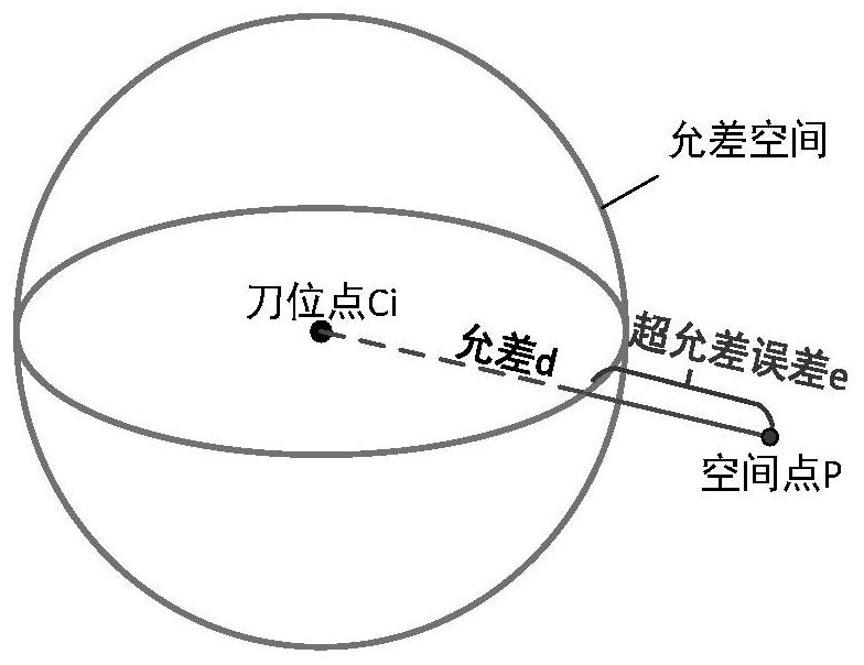
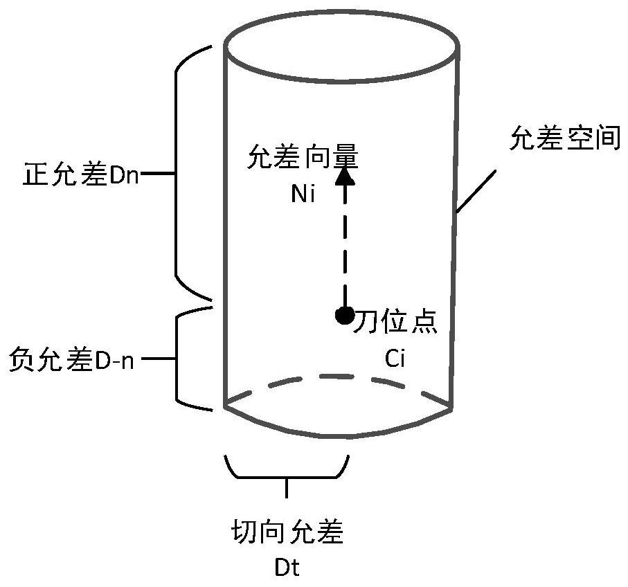
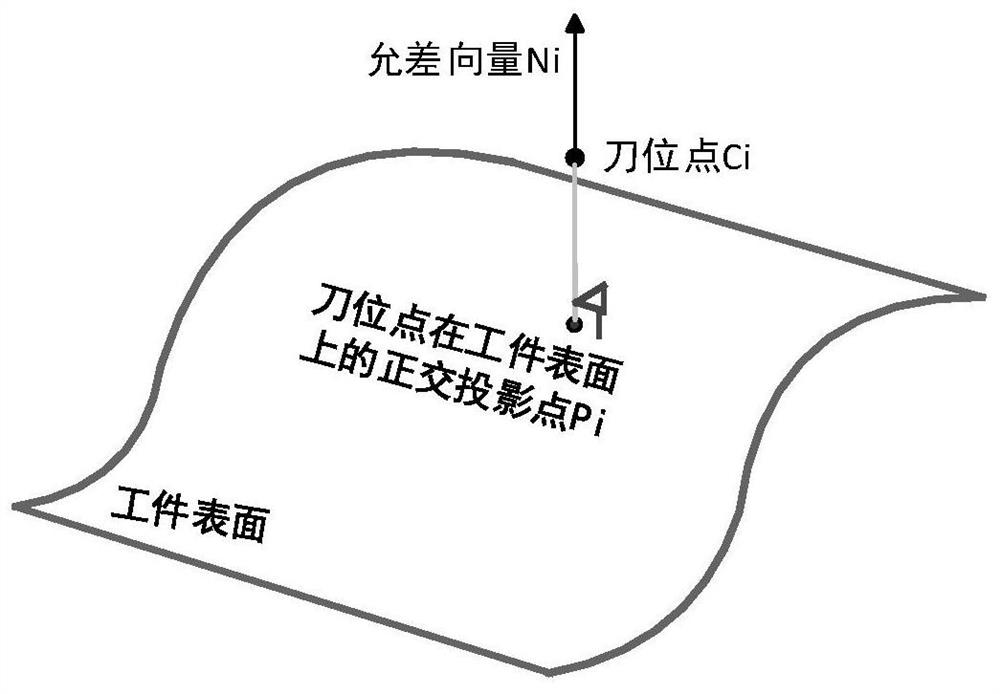
[0064] (1) Firstly, the tolerance space (Tolerance Space, TS) is defined as the space formed by the position of the tool point that can be adjusted to meet the error requirements. Define the Over Tolerance Error (Over Tolerance Error, OTE) as the distance from any spatial point to the outer surface of...


PUM


Abstract

The invention discloses a multi-axis track compression method for multiple machining scenes, which belongs to the field of numerical control machining. According to the method, parameter synchronization between a tool nose track and a tool shaft track is carried out by adopting a C2 continuous cubic rational spline which ensures monotonicity, the C2 continuity ensures continuous change of a tool shaft vector, the acceleration is continuous, a rotating shaft moves to enable the acceleration to be continuous; and due tomonotonicity, the cutter shaft point spline parameters are ensured to be increased or unchanged along with increasing of the cutter point spline parameters, and the condition that the cutter shaft point retreats is avoided. According to the method, decoupling of error calculation and a track compression method is achieved, when a new processing scene appears, only a new allowance space and a corresponding OTE calculation method need to be designed, and any step in the track compression process does not need to be modified. According to the method, the target compression ratio is combined with the feature curvature integral, iteration is not needed, the effect of rapidly selecting the initial fitting node can be achieved, and the compression efficiency is improved.

Description

technical field [0001] The invention belongs to the field of numerical control machining, and more specifically relates to a multi-axis trajectory compression method for multi-processing scenes. Background technique [0002] In the field of CNC machining, in order to obtain a multi-axis machining program, it is first necessary to use CAM (Computer Aided Manufacturing) software to generate a machining trajectory based on the part model and combined with process parameters, and then discretize it. Therefore, a multi-axis machining program is usually composed of G01 small line segments , which will lead to the following defects: only G0 continuity is achieved between adjacent small line segments, which will lead to fluctuations in feed speed and acceleration during processing, causing vibration of the machine tool and deterioration of processing quality. At the same time, in order to achieve higher machining accuracy, sometimes the small line segment of G01 is very short, which...

Claims


Application Information

Patent Timeline
IPC IPC(8): G05B19/408
CPCG05B19/4086G05B2219/35356
Inventor 杨建中刘雨康周会成高嵩朱万强杨少军
Owner HUAZHONG UNIV OF SCI & TECH
Learn More