Multi-link synchronous access throughput optimization method, system terminal and medium

An optimization method and throughput technology, applied in wireless communication, electrical components, etc., can solve the problem of uncertain number of links, multi-link synchronous access throughput performance limit and unclear optimization method, and low utilization efficiency of wireless spectrum resources and other issues to achieve the effect of improving performance and improving utilization efficiency

Active Publication Date: 2021-10-01
HUAZHONG UNIV OF SCI & TECH
View PDF8 Cites 0 Cited by
  • Summary
  • Abstract
  • Description
  • Claims
  • Application Information

AI Technical Summary

Problems solved by technology

[0003] Through the above analysis, the problems and defects of the existing technology are: the throughput performance limit and optimization method of multi-link synchronous access are still unclear, which greatly affects the performance of the multi-link mechanism
[0004] Moreover, in the prior art, the performance of the WiFi 7 network is not improved by maximizing the network throughput, resulting in low utilization efficiency of wireless spectrum resources
[0005] The difficulty in solving the above problems and defects is: due to the complex multi-link synchronous access strategy and the uncertain number of links, the traditional WiFi random access model is difficult to apply to multi-link synchronous access, so there is currently no multi-link synchronous access model. Theoretical analysis model for modeling synchronous access of roads
In the absence of a theoretical basis, it is impossible to obtain the throughput performance limit of multi-link synchronous access networks in general, and it is also impossible to obtain a fast optimization method suitable for any network

Method used


Image

  • Multi-link synchronous access throughput optimization method, system terminal and medium
  • Multi-link synchronous access throughput optimization method, system terminal and medium
  • Multi-link synchronous access throughput optimization method, system terminal and medium

Examples


Embodiment Construction

[0049] In order to make the object, technical solution and advantages of the present invention more clear, the present invention will be further described in detail below in conjunction with the examples. It should be understood that the specific embodiments described here are only used to explain the present invention, not to limit the present invention.

[0050] Aiming at the problems existing in the prior art, the present invention provides a WiFi 7 multi-link synchronous access throughput optimization method and system. The present invention will be described in detail below in conjunction with the accompanying drawings.

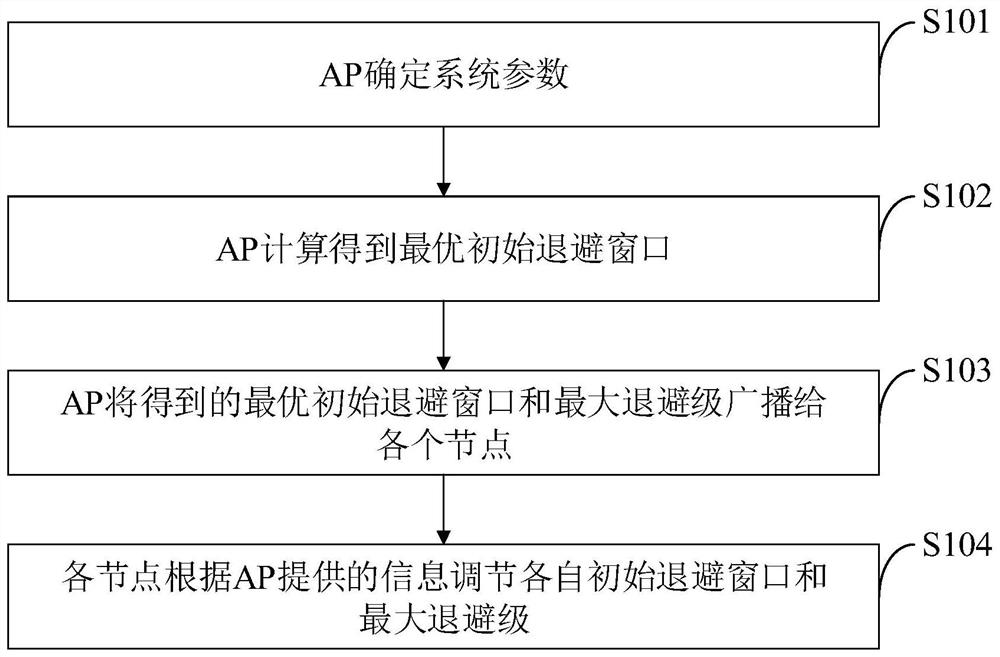
[0051] Such as figure 1 As shown, the WiFi 7 multi-link synchronous access throughput optimization method provided by the embodiment of the present invention includes the following steps:

[0052] S101, the AP determines system parameters;

[0053] S102, the AP calculates and obtains the optimal initial backoff window;

[0054] S103, the AP broadcasts...


PUM


Abstract

The invention belongs to the technical field of wireless local area networks, and discloses a multi-link synchronous access throughput optimization method, a system terminal and a medium, and the multi-link synchronous access throughput optimization method comprises the following steps that an AP determines system parameters; the AP calculates an optimal initial backoff window; the AP broadcasts the obtained optimal initial backoff window and the maximum backoff level to each node; and each node adjusts respective initial back-off window and maximum back-off level according to the information provided by the AP. According to the method, a throughput model of the WiFi 7 multi-link network is obtained through Markov process analysis, and an initial backoff window of the WiFi 7 multi-link network is dynamically adjusted according to system parameters so as to achieve the maximum throughput; the WiFi 7 multi-link network performance is improved by maximizing the network throughput, the utilization efficiency of wireless spectrum resources is improved, and the method is suitable for two access strategies of longest back-off access and shortest back-off access and any number of links including a single link.

Description

technical field [0001] The invention belongs to the technical field of wireless local area networks, and in particular relates to a multi-link synchronous access throughput optimization method, a system terminal and a medium. Background technique [0002] At present, the IEEE 802.11 standard, that is, the WiFi standard is currently the most widely used WLAN physical layer and medium access control layer standard, and WiFi has almost become a synonym for WLAN. With the rapid development of the mobile Internet, users have higher and higher requirements for WiFi networks. In order to meet the increasing traffic and higher quality of service requirements, IEEE continues to introduce new 802.11 standard amendments to improve the performance of WiFi networks. In 2019, IEEE started research on the next-generation WiFi standard, WiFi 7. WiFi 7 will introduce a major improvement - the multi-link mechanism. In order to reduce the interference between links, multi-link devices need ...

Claims


Application Information

Patent Timeline
IPC IPC(8): H04W24/02H04W24/06H04W74/08
CPCH04W24/02H04W24/06H04W74/08
Inventor 高雅玙张杰
Owner HUAZHONG UNIV OF SCI & TECH
Why Eureka
Try Eureka