Lamp metal piece polishing device

A technology of polishing device and metal parts, applied in grinding/polishing safety device, grinding drive device, metal processing equipment, etc., can solve the problems of loud noise, low hardness of metal parts, affecting the appearance and optical performance of metal parts, etc. Achieve the effect of reducing energy consumption and ensuring polishing accuracy

Active Publication Date: 2021-10-08
南通兴胜灯具制造有限公司
View PDF5 Cites 0 Cited by
  • Summary
  • Abstract
  • Description
  • Claims
  • Application Information

AI Technical Summary

Problems solved by technology

[0002] In order to improve the overall aesthetics and optical performance of the metal parts in LED lamps, they are generally polished before assembly. At present, the existing polishing devices for metal parts in lamps still have some shortcomings when they are used, and the polishing technology is still The traditional one-moving-one-static technology is used, that is, the polishing wheel moves towards the metal parts of the lamps to be processed. Due to the limitation of use, the hardness of the metal parts for lamps is low, and the moment when the static metal parts are in contact with the polishing wheel is easily affected by the impact. The deformation occurs due to the large force, which seriously affects the appearance and optical performance of the metal parts, and during the polishing process, metal shavings and noise are likely to be generated. Although there is a dust suction mechanism around the polishing wheel, the metal shavings are still lingering in the polishing process. around the wheel, and has a large noise, which makes it difficult for the staff to observe the working status of the polishing wheel at close range. Therefore, at this stage, there is an urgent need for a lamp metal polishing device to solve the above problems

Method used


Image

  • Lamp metal piece polishing device
  • Lamp metal piece polishing device
  • Lamp metal piece polishing device

Examples


Embodiment Construction

[0030]The technical solutions in the embodiments of the present invention will be clearly and completely described below with reference to the accompanying drawings in the embodiments of the present invention. Obviously, the described embodiments are only a part of the embodiments of the present invention, but not all of the embodiments. Based on the embodiments of the present invention, all other embodiments obtained by those of ordinary skill in the art without creative efforts shall fall within the protection scope of the present invention.

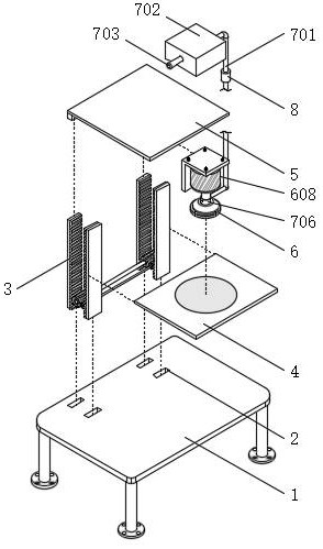
[0031] see Figure 1-9 , The lamp metal parts polishing device in the figure includes: a metal part processing table 1 for sliding connection of the linkage assembly 3; a plurality of sliding connection ports 2 for preventing the linkage assembly 3 from lifting and lowering along the vertical direction. A plurality of sliding connection ports 2 for swinging of the movable stage 4 and the ceiling 5 are opened on the top of the metal par...


PUM


Abstract

The invention discloses a lamp metal piece polishing device which comprises a metal piece machining table used for being in sliding connection with a linkage assembly, and multiple sliding connecting ports used for preventing a movable objective table and a ceiling from shaking and swinging in the process that the linkage assembly ascends and descends in the vertical direction, wherein the multiple sliding connecting ports are formed in the top of the metal piece machining table. According to the lamp metal piece polishing device provided by the invention, through the interwork of the designed linkage assembly, a drainage and dust removal assembly, an aeroionization assembly and other structures, scrap metal is prevented from effusing into the surrounding air; noise generated between a polishing wheel and a lamp metal part to be machined can be isolated by the aid of a sound insulation type separation brush; on one hand, air flow through which electric power of an electric field flows is utilized, on the other hand, electric energy is provided for a first electrode plate and a second electrode plate, air flow carrying the scrap metal is ionized, and the first electrode plate and the second electrode plate absorb electrified dust, so that dust removal operation is achieved; and a power source does not need to be additionally introduced, so that the function of reducing energy consumption is achieved.

Description

technical field [0001] The invention relates to the technical field of lighting equipment processing, in particular to a polishing device for metal parts of lamps. Background technique [0002] In order to improve the overall appearance and optical performance of the metal parts in LED lamps, they are generally polished before assembly. At present, the existing polishing devices for metal parts of lamps still have some shortcomings in use, and the polishing technology is still in use. The traditional one-motion-one-static technique is adopted, that is, the polishing wheel moves to the direction close to the metal part of the lamp to be processed. Due to the limitation of use, the hardness of the metal part for the lamp is low, and the static metal part is easily affected by the impact at the moment of contact with the polishing wheel. The deformation occurs due to the large force, which seriously affects the appearance and optical performance of the metal parts, and during t...

Claims


Application Information

Patent Timeline
Patent Type & Authority Applications(China)
IPC IPC(8): B24B29/02B24B27/02B24B55/06B24B27/00B24B41/06B24B47/12
CPCB24B29/02B24B27/02B24B55/06B24B27/0046B24B41/06B24B47/12
Inventor 颜德新
Owner 南通兴胜灯具制造有限公司
Why Eureka
Try Eureka