Supercharge Your Innovation With Domain-Expert AI Agents!

A transmission line fault location method, recording medium and data processing device

A transmission line and fault location technology, which is applied to the fault location and uses the pulse reflection method to detect faults, etc., can solve the problems of fault location accuracy constraints, internal hidden dangers are difficult to be discovered and checked in time, and lack of source, etc., to improve detection resolution Power and accurate prediction and evaluation capabilities, lower maintenance technical threshold, and the effect of reducing data redundancy

Active Publication Date: 2022-05-03
WUHAN NARI LIABILITY OF STATE GRID ELECTRIC POWER RES INST
View PDF2 Cites 0 Cited by
  • Summary
  • Abstract
  • Description
  • Claims
  • Application Information

AI Technical Summary

Problems solved by technology

Due to the special laying method of laying underground, its state is not observable, and internal hidden dangers are difficult to be discovered and checked in time. In particular, underground communication signals are restricted, and the accuracy of fault location is severely restricted.
At present, power supply companies mostly adopt passive protection measures to solve hidden dangers of underground transmission lines, such as installing waterproof, fireproof / explosion-proof sealing, etc. In extreme cases, personnel are required to guard and guard, and there is a lack of source and systemic targeting of integrated power utility tunnel equipment. Ontology Security Technical Solutions

Method used


Image

  • A transmission line fault location method, recording medium and data processing device
  • A transmission line fault location method, recording medium and data processing device
  • A transmission line fault location method, recording medium and data processing device

Examples


Embodiment Construction

[0025] In order to make the purpose, technical solutions and advantages of the embodiments of the present invention more clear, the following will describe the technical solutions in the embodiments of the present invention in conjunction with the drawings in the embodiments of the present invention, and the described embodiments are part of the embodiments of the present invention , but not all examples. Based on the embodiments of the present invention, all other embodiments obtained by those skilled in the art without innovative efforts fall within the protection scope of the present invention.

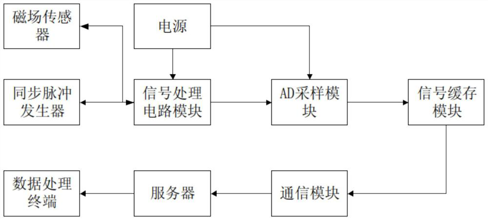
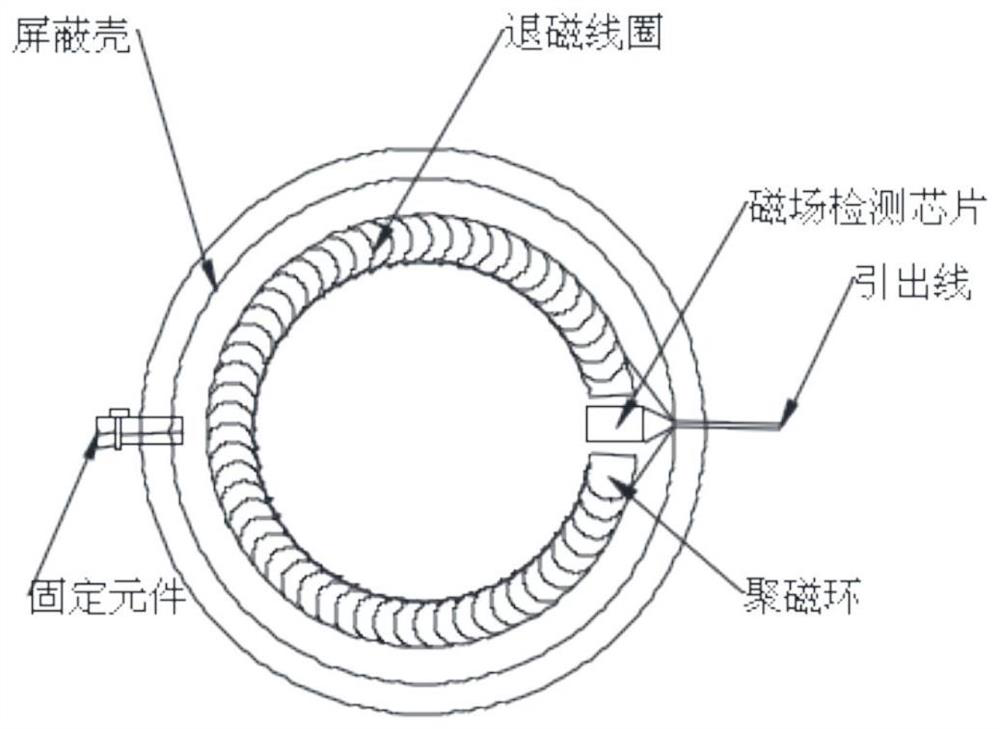
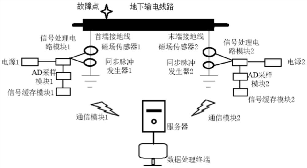
[0026] like Figure 1~3 As shown, a ground current monitoring and fault location system of an underground transmission line according to the present invention includes:

[0027] The power supply is used to provide the voltage required for the system to work.

[0028] The power supply can be taken from the body of the underground transmission line through a transformer, or it can ...


PUM


Abstract

The invention belongs to the technical field of electrician detection, and discloses a transmission line fault location method, comprising: respectively installing two magnetic field sensors and two synchronous pulse generators on the grounding wires at the head and end of the power transmission line; the synchronous pulse generator at the head end Send a synchronous pulse to the end, and after the magnetic field sensor at the end senses the synchronous pulse, the synchronous pulse generator at the end sends the same pulse to the first end; record the time points when the synchronous pulse is sent and received at the first end and the end respectively, and calculate the transmission line for this section The time t it takes to transmit a sync pulse c ; Calculate the time difference t between the head and end magnetic field sensors receiving the electromagnetic field mutation signal formed by the current distortion on the grounding line o ; use t o , t c And the known line length to characterize the location of the fault point. The present invention also provides a non-transient readable recording medium storing a transmission line fault location program and a device containing the medium. The program can be invoked by a processing circuit to execute the aforementioned method, which is suitable for solving the problem of hidden line fault point location .

Description

technical field [0001] The invention belongs to the technical field of electrician detection, and specifically discloses a transmission line fault location method, a non-transient readable recording medium and a data processing device. Background technique [0002] The municipal utility tunnel space built by the urban comprehensive utility gallery in the underground of the city gathers municipal utility pipelines such as electric power, communication, and water supply in one structure according to planning requirements, and implements unified planning, design, construction, and management. It has completely changed the chaotic situation in which each pipeline was constructed and managed separately in the past. When the pipeline needs to be repaired, there is no need to excavate the road. The maintenance personnel and engineering vehicles only need to enter the underground pipe gallery from the maintenance channel to start construction. It will not affect the road traffic, bu...

Claims


Application Information

Patent Timeline
Patent Type & Authority Patents(China)
IPC IPC(8): G01R31/11
CPCG01R31/11Y04S10/52
Inventor 张静江翼杨旭徐惠黄立才吴念刘梦娜李梦齐
Owner WUHAN NARI LIABILITY OF STATE GRID ELECTRIC POWER RES INST
Features
  • R&D
  • Intellectual Property
  • Life Sciences
  • Materials
  • Tech Scout
  • Unparalleled Data Quality
  • Higher Quality Content
  • 60% Fewer Hallucinations
Learn More