Biopsy needle cleaning device
A technology for cleaning devices and biopsy needles, which is applied to cleaning hollow objects, cleaning methods and utensils, cleaning methods using liquids, etc., can solve problems such as easy to be stabbed in operation, hidden safety hazards, and reduced cleaning efficiency, so as to improve the efficiency of cleaning The effect of improving the safety factor of equipment and improving the cleaning effect
- Summary
- Abstract
- Description
- Claims
- Application Information
AI Technical Summary
Problems solved by technology
Method used
Image

Examples
Embodiment Construction
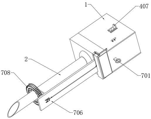
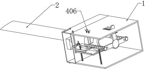
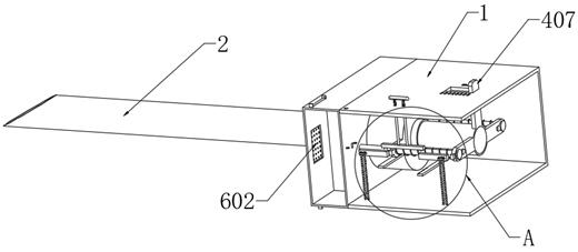
[0035] The implementation of the present invention is described below through specific specific examples, and those skilled in the art can understand the advantages and effects of the present invention from the content disclosed in this specification. It should be noted that the diagrams provided in the following examples are for illustrative purposes only, and are only schematic diagrams rather than actual pictures, and should not be construed as limitations on the present invention. In order to better illustrate the embodiments of the present invention , some components in the figure will be omitted, enlarged or reduced, and do not represent the size of the actual product; for those skilled in the art, it is understandable that some known structures and their descriptions in the figure may be omitted.
[0036]The same or similar symbols in the figures of the embodiments of the present invention correspond to the same or similar components. In the description of the present in...
PUM
 Abstract
Description
Claims
Application Information
 - R&D
- Intellectual Property
- Life Sciences
- Materials
- Tech Scout
- Unparalleled Data Quality
- Higher Quality Content
- 60% Fewer Hallucinations
Browse by: Latest US Patents, China's latest patents, Technical Efficacy Thesaurus, Application Domain, Technology Topic, Popular Technical Reports.
© 2025 PatSnap. All rights reserved.Legal|Privacy policy|Modern Slavery Act Transparency Statement|Sitemap|About US| Contact US: help@patsnap.com