
Pyrolyzing furnace non-condensable gas collecting, pressure-stabilizing, utilizing and treating method

A treatment method and pyrolysis furnace technology, which is applied in the fields of combustible gas purification, combustible gas purification/transformation, petroleum industry, etc., and can solve problems such as difficulty in returning non-condensable gas to the furnace, irregular gas volume, and difficulty in tail gas treatment. , to achieve the effect of solving the difficulty of exhaust gas treatment, high degree of safety design and stable pressure

Pending Publication Date: 2021-10-12
HUNAN VARY TECH
View PDF3 Cites 0 Cited by
  • Summary
  • Abstract
  • Description
  • Claims
  • Application Information

AI Technical Summary

Problems solved by technology

The amount of non-condensable gas generated during continuous pyrolysis is irregular, and the pressure inside the pyrolysis furnace is controlled at a micro-negative pressure of ±500Pa, which makes it difficult to return the non-condensable gas to the furnace for utilization. Enterprises need to invent a set of non-condensable gas collection, Pressure stabilization utilization system and method to maintain stable pressure in pyrolysis furnace and stable recovery and utilization of non-condensable gas
The non-condensable gas from the pyrolysis furnace is usually acidic and easy to corrode the equipment, resulting in short service life of the equipment and difficulty in tail gas treatment

Method used


Image

  • Pyrolyzing furnace non-condensable gas collecting, pressure-stabilizing, utilizing and treating method
  • Pyrolyzing furnace non-condensable gas collecting, pressure-stabilizing, utilizing and treating method
  • Pyrolyzing furnace non-condensable gas collecting, pressure-stabilizing, utilizing and treating method

Examples


Embodiment Construction

[0017] It should be noted that, in the case of no conflict, the embodiments of the present invention and the features in the embodiments can be combined with each other. The present invention will be described in detail below with reference to the accompanying drawings and examples.

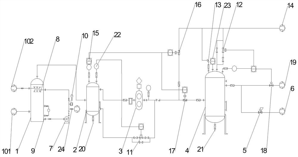
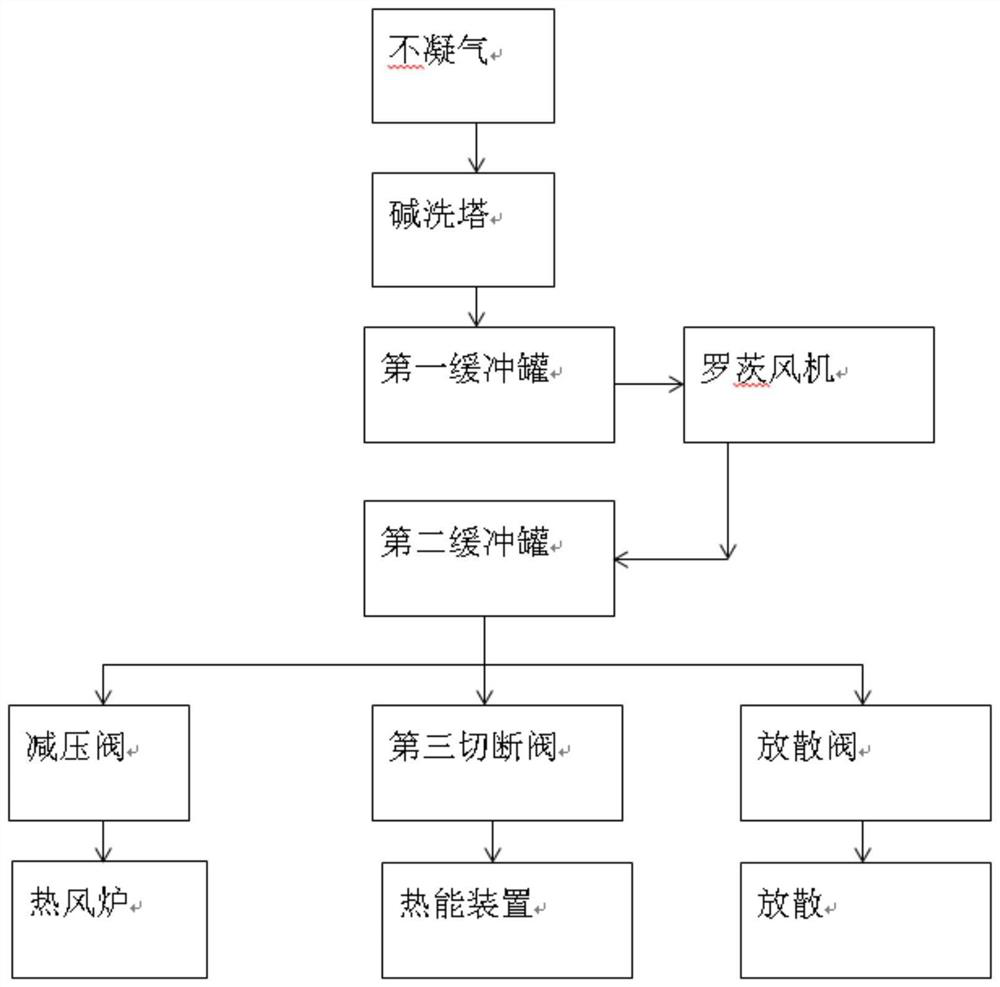
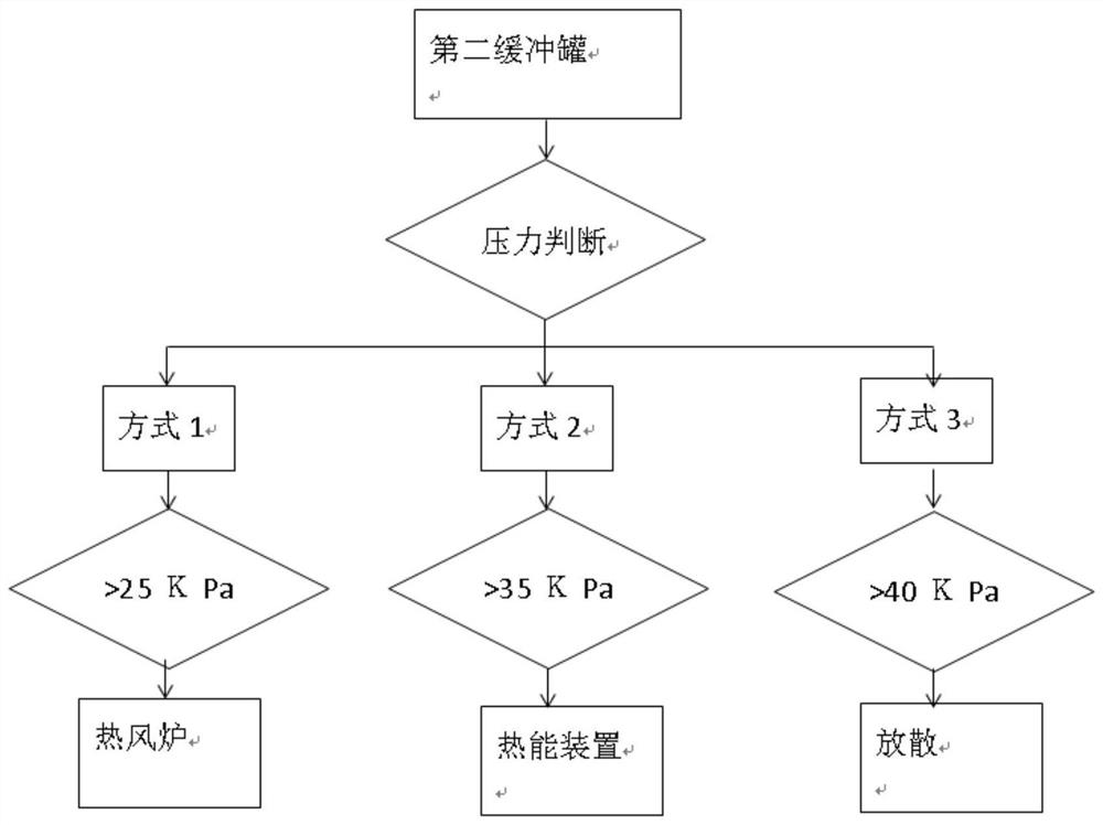
[0018] The present invention is described further in conjunction with accompanying drawing, as figure 1 , figure 2 As shown, the working process of a system for collecting and stabilizing the non-condensable gas of the pyrolysis furnace is as follows: first, the non-condensable gas is washed with alkali to remove acid, and the non-condensable gas generated by the pyrolysis process enters the alkali-wash tower, and is sprayed by alkali-wash The pump circulates and sprays the lye to remove the acid gas in the non-condensable gas. During the cyclic spraying process, an online pH meter is used to detect the concentration of the lye. When the pH value of the lye is 12, close the waste liquid valve, ...


PUM


Abstract

The invention discloses a pyrolyzing furnace non-condensable gas collecting, pressure-stabilizing, utilizing and treating method, which comprises: allowing non-condensable gas generated by a pyrolysis furnace to enter an alkaline washing tower through a gas inlet, carrying out a neutralization reaction to remove acidic materials in the non-condensable gas, and allowing the non-condensable gas to enter a first buffer tank for buffer storage; adopting a Roots blower to pressurize and convey the non-condensable gas in the first buffer tank into a second buffer tank for buffering; and conveying the non-condensable gas cached in the second buffer tank to a hot blast stove in the pyrolyzing furnace through a pressure reducing valve for combustion and heat supply. The non-condensable gas does not corrode equipment during combustion after being deacidified by the alkaline washing tower, and meanwhile, the problems of difficulty in tail gas treatment and the like are solved. A collecting, pressure-stabilizing, utilizing and treating system for the non-condensable gas is high in automation degree, high in safety design degree and easy to operate. The pressure in the pyrolyzing furnace can be effectively controlled to be stable, and the gas of the hot blast stove is stably and uniformly conveyed, so that the whole pyrolyzing system continuously and stably runs.

Description

technical field [0001] The invention relates to the technical field of pyrolysis and gasification, in particular to a treatment method for collecting, stabilizing, and utilizing non-condensable gas in a pyrolysis furnace. Background technique [0002] The organic solid waste is gasified through the pyrolysis furnace to complete the pyrolysis process, producing pyrolysis oil, pyrolysis water and non-condensable gas. Pyrolysis oil and non-condensable gas are used as renewable energy, so as to achieve the purpose of recycling organic solid waste resources by using pyrolysis process. Among them, the main components of non-condensable gas are: methane, hydrogen, carbon monoxide, ethane, acetylene, butane and other combustible gases below carbon five, with a calorific value of more than 10,000 calories per standard square meter, and a calorific value higher than natural gas 1500-2000 card / Nm 3 , is a very good regenerative gas energy source. The non-condensable gas produced by p...

Claims


Application Information

Patent Timeline
Patent Type & Authority Applications(China)
IPC IPC(8): C10K1/12
CPCC10K1/12
Inventor 明果英李昌乐左志越刘芳玉
Owner HUNAN VARY TECH
Learn More