Positioning calibration method for construction working machines and positioning calibration controller thereof

A technology for working machinery and positioning correction, which is applied to mechanically driven excavators/dredgers, satellite radio beacon positioning systems, instruments, etc. Eliminate pasting errors and their accumulation, save input time, and reduce the effect of pasting parts

Active Publication Date: 2021-10-12
综合追求有限责任公司
View PDF10 Cites 0 Cited by
  • Summary
  • Abstract
  • Description
  • Claims
  • Application Information

AI Technical Summary

Problems solved by technology

First, the measurement of body size is particularly difficult and complicated
For example, a prism is pasted in multiple places, and pasting errors occur at various places, and these errors accumulate
In addition, although it is a problem in the actual structure of the body, there are unevenness (concave-convex) on the surface, and it is difficult to accurately measure the length in the horizontal direction and the vertical direction.
In particular, the calibration takes a lot of effort and is complicated, and it is necessary to understand the calibration method, and it is not easy for general users (operators) to perform it widely.
In addition, the level of the body during calibration is often set on site, so accuracy cannot be required in principle
When shipped from the factory, it can be measured with a precise averaging table, but it is difficult to pursue accuracy in daily use in the field
In this way, there are many constraints and technical problems in the positioning and correction of construction machinery, and the above technical problems have not been fundamentally solved.

Method used


Image

  • Positioning calibration method for construction working machines and positioning calibration controller thereof
  • Positioning calibration method for construction working machines and positioning calibration controller thereof
  • Positioning calibration method for construction working machines and positioning calibration controller thereof

Examples


Embodiment 1

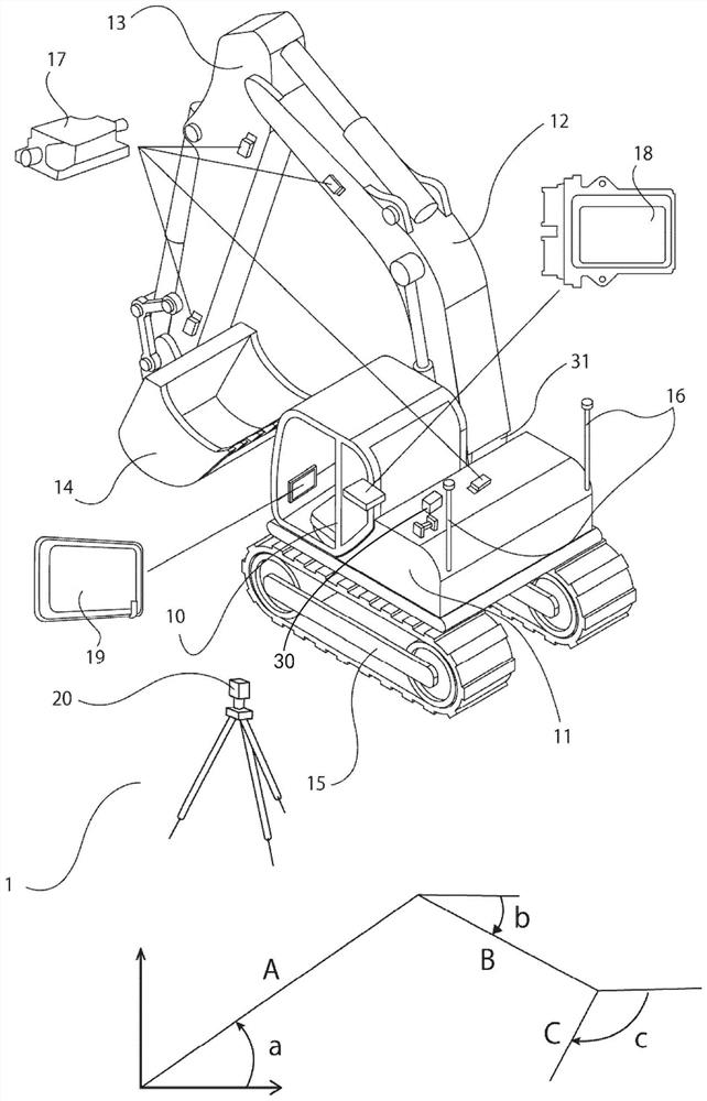
[0137] First, a rotational measurement of the driven work tool is performed. This is an operation to continue setting and correcting the body coordinate system. Such as Figure 7 As shown, for example, a prism is held at the bucket tip 25 and the World Geodetic System coordinates 3 of the tip are measured by a total station (TS) 6 . Measurements are taken from the side of the backhoe. Since only the lateral position is measured from the TS at the same depth, stabilization of accuracy can be expected.

[0138] ·Such as Figure 8 As shown, the boom 12 and the arm 13 are fixed, and only the bucket 14 is rotated, and the 2P of the bucket tip 25 is measured in the world geodetic system i .

[0139] • The arm 13 is rotated, and the above operation is performed. There are four measurement points in total.

[0140] • Next, the boom 12 is rotated, and the above operation is repeated. There are a total of eight measurement points.

[0141] ·For boom 12, arm 13, bucket 14 at the...

Embodiment 2

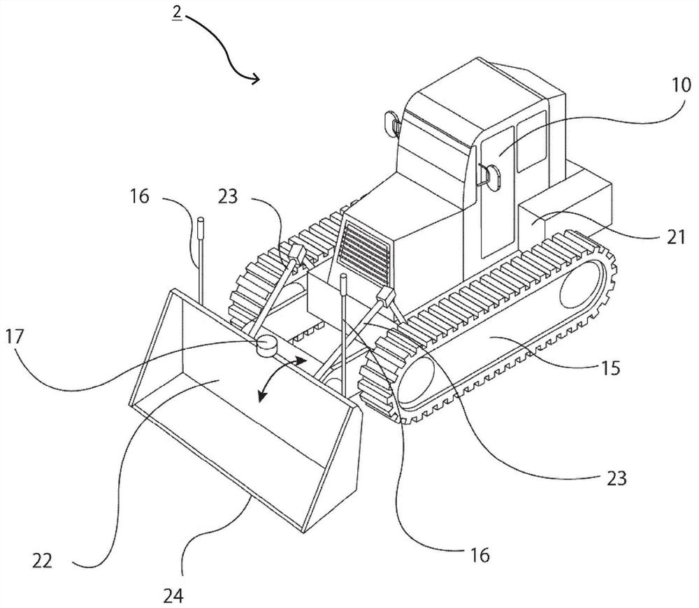
[0157] Next, an example of a bulldozer will be described.

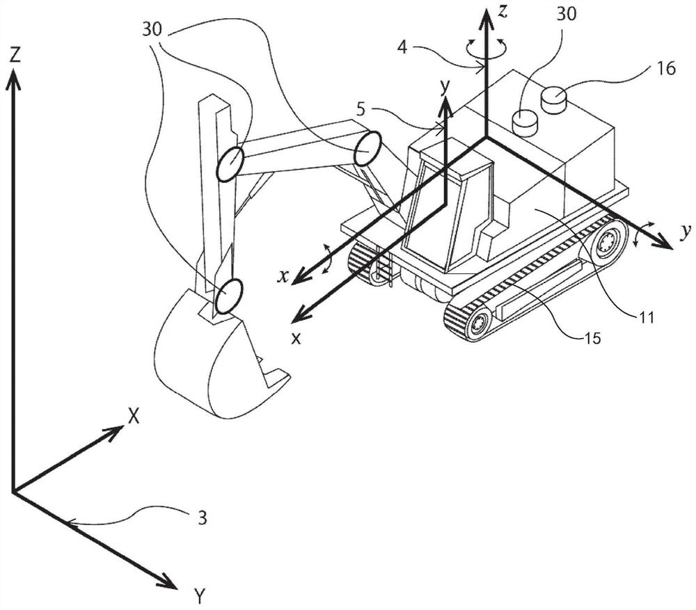
[0158] Figure 4 It is a three-dimensional conceptual diagram showing the form of the coordinate system of the bulldozer as a whole in the positioning correction method of the construction work machine and its positioning correction controller according to an embodiment of the present invention. As shown in this figure, a group of GNSS receivers 16 and antennas are arranged on the body (as shown in this figure, the GNSS receivers 16 and antennas may also be integrated). An IMU (Inertial Measurement Unit, inertial measurement unit) 30 composed of a three-axis acceleration sensor and a three-axis gyro sensor is provided on the body. These are placed on the upper body main body 21 on the body.

[0159] Such as Figure 4 As shown, the same IMU is set on the blade (dozing blade) 22 . The operation structure of the scraper is based on a rotating shaft near the center of the body, and the frame (thrust arm) 23 is rotated...


PUM


Abstract

A positioning calibration method for a construction working machine and a positioning calibration controller thereof are provided for measuring and calibrating the configuration dimensions of the construction working machine. The construction working machine has an machine body including a first surveying device for surveying the position coordinates and a movable working tool including one or more angle detecting devices. The method and the controller are characterized in that the configuration dimensions and the configuration positions of the movable business tool are specified by the position measurement data and the angle data detected by the angle detecting device by measuring the position coordinates of the plurality of posture positions of the movable business tool by a second surveying device.

Description

technical field [0001] The invention relates to a positioning and calibration method of a construction operation machine, in particular to the simplification and high-precision calibration of GNSS position detection of a movable operating part. Background technique [0002] Conventionally, in the fields of civil engineering and construction, backhoes have been used as construction work machines when performing ground preparation, paving, and the like. Backhoes are also known as hydraulic excavators. In recent years, in the operation of this backhoe, the machine guidance control, that is, the movement of the specified body or the boom as the upper driving body (also called movable working part or movable working tool, driving working tool), The drive and rotation of the arm, bucket, etc. are automatically controlled according to the shape of the site preparation, or the operator is assisted in the operation. In order to perform such control, it is necessary to accurately gr...

Claims


Application Information

Patent Timeline
Patent Type & Authority Applications(China)
IPC IPC(8): E02F3/32E02F3/36E02F3/43E02F3/76E02F3/84G01C21/16G01C25/00G01S19/42
CPCE02F3/32E02F3/36E02F3/435E02F3/76E02F3/84G01C25/00G01S19/42G01C21/165G01C15/00E02F9/264G01S19/235G01S19/23
Inventor 玉里芳直
Owner 综合追求有限责任公司
Why Eureka
Try Eureka