Back rib type composite board

A composite board and back rib type technology is applied in the field of composite boards to achieve the effects of improving utilization, strong strength and enhancing product practicability

Inactive Publication Date: 2021-10-12
有嘉(山东)新材料科技有限公司
View PDF1 Cites 0 Cited by
  • Summary
  • Abstract
  • Description
  • Claims
  • Application Information

AI Technical Summary

Problems solved by technology

[0006] Aiming at the deficiencies of the prior art, the present invention provides a rib-backed composite panel, which has the advantages of reinforcement and fixation, and solves the above-mentioned problems

Method used


Image

  • Back rib type composite board
  • Back rib type composite board
  • Back rib type composite board

Examples


Embodiment 1

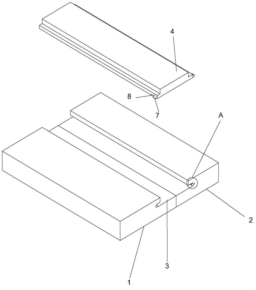
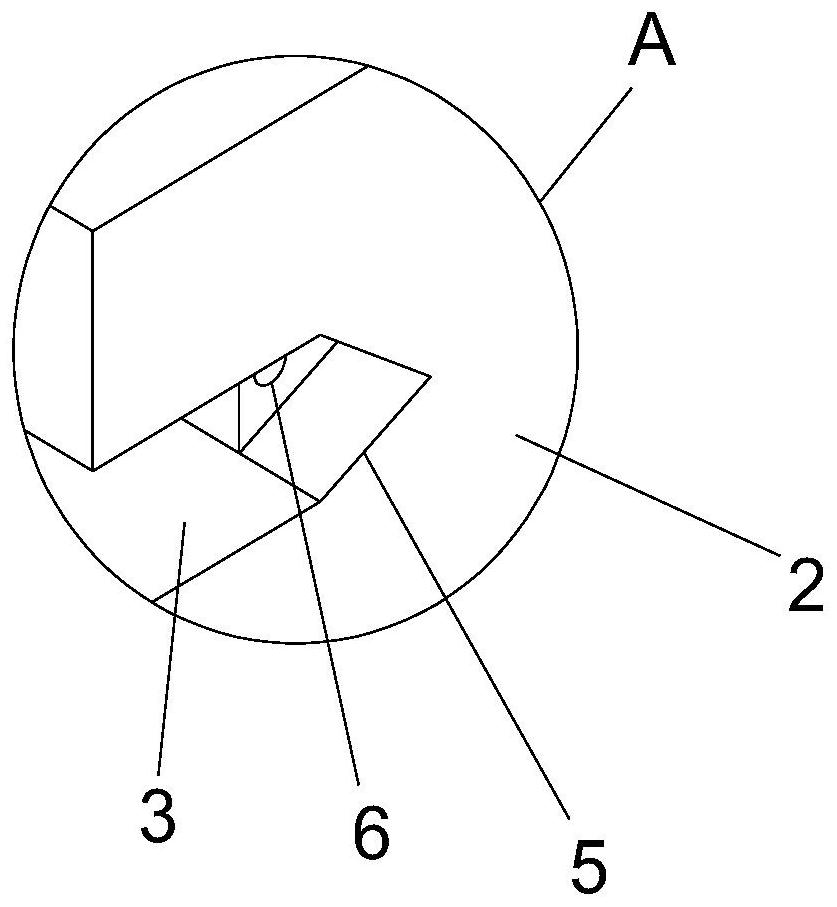
[0036] A back-reinforced composite panel, please refer to Figure 1-4 , including A board 1 and B board 2, the sides of A board 1 and B board 2 are closely attached, and a back board 4 is compounded on the back of the joint line of A board and B board, A board 1 and B board 2 The bottom of the adjacent side is symmetrically provided with an "L"-shaped card slot 3, and the inside of the two card slots 3 is connected with a back plate 4 with a "convex" shape in section, and the back plate 4 is compatible with the inside of the two card slots 3 Matched and fixed by adhesive, the adjacent side of A board 1 and B board 2 is provided with a connection groove 5 communicating with the card groove 3, the inside of the connection groove 5 is provided with a connection hole 6, and the two ends of the back board 4 are fixedly installed with The connection block 7 corresponding to the connection groove 5, the two connection blocks 7 are installed with the clamping column 8 that can be enga...

Embodiment 2

[0042] Embodiment two: on the basis of embodiment one, refer to Figure 1-3 There are cable grooves 14 on the side of plate A 1, two cable grooves 14 form a group, and the interior of each group of "L" shaped cable grooves 14 extends away from each other, and the interior of board B 2 corresponding to cable grooves 14 is inlaid with Anchor piece 15, the anchor piece 15 is "U" shape, and the two ends of the anchor piece 15 extend through the inside of the B board 2 and extend outward toward the direction away from each other. adaptation.

[0043] Working principle: When board A 1 and board B 2 are docked, after the two ends of the anchor 15 are squeezed to the middle, insert the two ends of the anchor 15 into the corresponding cable groove 14, when the anchor 15 is inserted into the corresponding cable groove 14 After the internal post-recovery deformation is clamped to both ends of the cable groove 14, the two ends of the anchor piece 15 recover and deform toward the inside o...

Embodiment 3

[0044] Embodiment three: on the basis of embodiment two, please refer to Figure 1-4 , The interior of the adjacent side of A board 1 and B board 2 is inlaid with a rectangular protective net 16, and the two ends of the anchor 15 inside the inlaid B board 2 first pass through the filter holes of the anchor 15 and then extend outward to B board 2 exterior.

[0045] Working principle: By setting the protective net 16 inside the A-board 1 and the B-board 2, the protective net 16 not only improves the overall shape strength of the board between the A-board 1 and the B-board 2, but also the protective net 16 is inlaid with the B-board 2. The inner anchor 15 further stabilizes the connection, strengthens the connection strength between the anchor 15 and the B board 2, indirectly promotes the connection strength between the A board 1 and the B board 2, and at the same time improves the connection between the A board 1, B board 2 and the back. The board 4 forms the overall board stre...


PUM


Abstract

The invention relates to the technical field of composite boards, and provides a back rib type composite board, which comprises a board A and a board B; the side surfaces of the board A and the board B are tightly attached; and a back board is compounded on the back surface of the attaching line of the board A and the board B. Through the fitting design of the board A, the board B and the back board, the composite connection strength is high; the situation that the connection strength of the composite board is poor due to dislocation fixation can be avoided; waste boards are utilized; the utilization rate of the boards is increased; the existing market conditions that large boards cannot be produced or are complex to process and small boards need to be specially customized in existing equipment are broken; the utilization rate of the waste boards used for the composite boards and the like is increased; and the product practicability is enhanced. In conclusion, the back rib type composite board in the invention has great popularization significance and market value.

Description

technical field [0001] The invention relates to the technical field of composite boards, in particular to a rib-backed composite board. Background technique [0002] Composite board refers to one layer of board covered with another board to achieve the effect of saving resources and reducing costs without reducing the use effect (anti-corrosion performance, mechanical strength, etc.). [0003] According to a Chinese patent (authorized publication number is CN210737987U) a snap-in type metal composite board, by opening a connection through hole with a snap-in groove on the metal core board, and at the same time, the surfaces of the metal plates on both sides are respectively provided with T-shaped Clamping structure, the T-shaped clamping structure is clamped in the connection through hole, so that a physical connection is formed between the surface metal plate and the metal core plate, ensuring the tightness of the connection between the surface metal plate and the metal cor...

Claims


Application Information

Patent Timeline
Patent Type & Authority Applications(China)
IPC IPC(8): F16S1/10E04B1/61E04B1/80E04C2/296E04C2/30
CPCF16S1/10E04B1/61E04B1/80E04C2/30E04C2/296
Inventor 陈盖
Owner 有嘉(山东)新材料科技有限公司
Why Eureka
Try Eureka