
Clamp body positioning mechanism suitable for turning and milling combined machining center

A composite processing and positioning mechanism technology, which is applied to metal processing machinery parts, positioning devices, manufacturing tools, etc., can solve problems such as unfavorable production efficiency, complicated process and time-consuming process, so as to avoid modification, improve versatility, and eliminate height positioning errors Effect

Active Publication Date: 2021-10-15
IKD CO LTD
View PDF8 Cites 1 Cited by
  • Summary
  • Abstract
  • Description
  • Claims
  • Application Information

AI Technical Summary

Problems solved by technology

It can be seen that the process is complicated and time-consuming, which is not conducive to the improvement of production efficiency

Method used


Image

  • Clamp body positioning mechanism suitable for turning and milling combined machining center
  • Clamp body positioning mechanism suitable for turning and milling combined machining center
  • Clamp body positioning mechanism suitable for turning and milling combined machining center

Examples


Embodiment Construction

[0040] Preferred embodiments of the present invention will be described in detail below with reference to the accompanying drawings. Those skilled in the art will appreciate that these descriptions are descriptive and exemplary only, and should not be interpreted as limiting the protection scope of the present invention.

[0041] It should be noted that similar reference numerals denote similar items in the following figures, therefore, once an item is defined in one figure, it may not be further defined and explained in subsequent figures.

[0042]In the description of the present invention, it should be noted that the orientation or positional relationship indicated by the terms "upper", "lower", "inner", "outer" etc. is based on the orientation or positional relationship shown in the drawings, or the The usual orientation or positional relationship of the invention product in use is only for the convenience of describing the present invention and simplifying the description...


PUM


Abstract

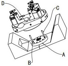
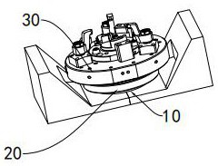
The invention discloses a clamp body positioning mechanism suitable for a turning and milling combined machining center. The clamp body positioning mechanism comprises a transition disc fixed to a machine tool working table, a clamp body used for clamping a workpiece and a plurality of positioning assemblies between the transition disc and the clamp body, wherein the positioning assembly comprises a lower positioning sleeve located at the top of the transition disc and an upper positioning piece located at the bottom of the clamp body, the lower positioning sleeve comprises an annular positioning piece with a positioning hole and an elastic piece, and the elastic piece is located below the annular positioning piece; the hole wall of the positioning hole is an annular inner conical surface which is gradually inclined to the center from top to bottom; an arc-shaped inclined surface matched with the annular inner conical surface is arranged on the outer wall of the upper positioning piece; the upper positioning piece extends into the positioning hole of the lower positioning sleeve in a pluggable manner, and the annular inner conical surface and the arc-shaped inclined surface abut against each other to play a positioning role; an elastic force of the elastic piece drives the annular positioning piece to float up and down to change the matching position of the annular inner conical surface and the arc-shaped inclined surface, thereby adjusting the positioning precision.

Description

technical field [0001] The invention relates to a processing fixture in the field of mechanical processing, in particular to a clamp body positioning mechanism suitable for a turning-milling compound machining center. Background technique [0002] The turning and milling compound machining center is a place where lathes and milling machines are processed together. It realizes the cutting process of the workpiece through the four basic movements of milling cutter rotation, workpiece rotation, milling cutter axial feed and radial feed, so that the workpiece can achieve high precision in terms of shape accuracy, position accuracy, and machined surface integrity. An advanced machining method that requires use. [0003] Further, when the workpieces are machined in the turning-milling compound machining center, they are all fixedly positioned on the tooling fixture, and the tooling fixture is then clamped on the machine tool of the turning-milling compound machining center. When...

Claims


Application Information

Patent Timeline
Patent Type & Authority Applications(China)
IPC IPC(8): B23Q3/06B23Q15/22
CPCB23Q3/06B23Q15/22
Inventor 乔子龙李超包方锋陈洪波高玉德章博延胡余俊周扬陈汉龙陈淑萍何齐丰桑志刚杨馀军黄秀勇
Owner IKD CO LTD
Learn More