Active-passive phase change heat storage and collection wall system

A technology of phase change heat storage and heat collecting wall, which is applied in the field of construction, can solve the problems of small vent area, heat entering the room, large thermal resistance, etc., and achieve the effect of reducing energy consumption and morbidity

Inactive Publication Date: 2021-10-15
DONGGUAN UNIV OF TECH
View PDF6 Cites 2 Cited by
  • Summary
  • Abstract
  • Description
  • Claims
  • Application Information

AI Technical Summary

Problems solved by technology

[0005] The purpose of the present invention is: the ability of the above-mentioned heat collecting wall system to use the temperature difference to create the chimney effect to drive the indoor air flow and ventilation is very limited, and it may cause excess heat to enter the room through the lower vent on the indoor side and the ordinary wall, which is not conducive to indoor Ventilation and cooling; when the outdoor temperature is low on rainy days in summer, because the heat collecting wall system cannot use solar radiation heat and the vent area is small, the overall thermal resistance of the structure is large, which is not conducive to the transfer of indoor heat to the outdoor cooling and indoor ventilation. Provide A method that makes full use of the natural cold source of low-temperature air at night, the cold air storage of air source heat pumps and the heat storage of electricity at night valley prices, actively adapts to summer climate and rainy weather, fully utilizes the ability of the heat collecting wall system to induce ventilation, and improves the passive ventilation and cooling potential of buildings Active and passive phase change heat storage wall system

Method used


Image

  • Active-passive phase change heat storage and collection wall system
  • Active-passive phase change heat storage and collection wall system

Examples


Embodiment Construction

[0016] The present invention will be described in further detail below in conjunction with accompanying drawing:

[0017] The preferred embodiments of the present invention will be described in detail below in conjunction with the accompanying drawings, so that the advantages and features of the present invention can be more easily understood by those skilled in the art, so as to define the protection scope of the present invention more clearly. The directional terms mentioned in the present invention, such as "up", "down", "front", "back", "left", "right", "top", "bottom", etc., are only for reference to the attached drawings. direction. Therefore, the directional terms used are used to illustrate and understand the present invention, but not to limit the present invention.

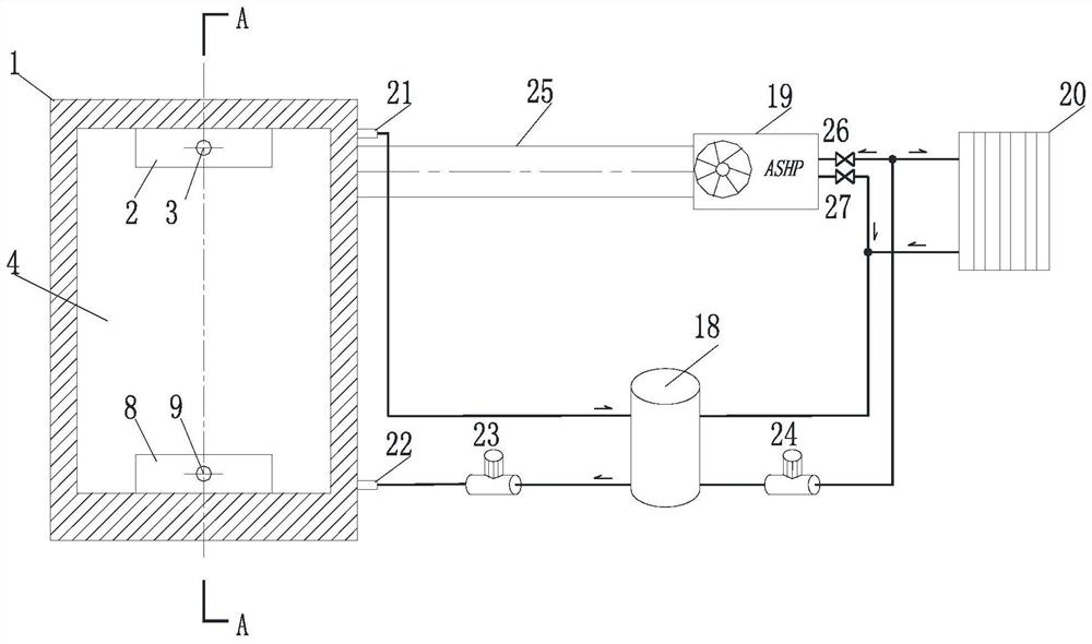
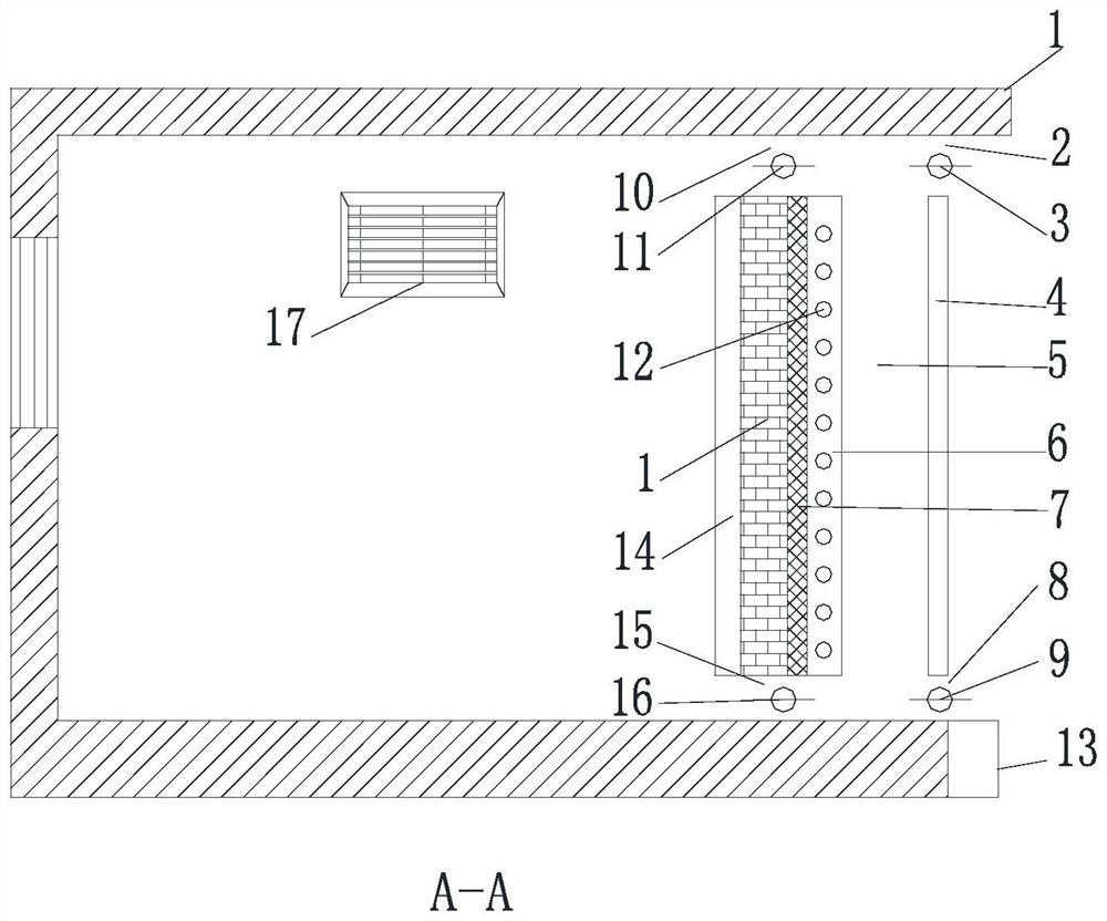
[0018] see figure 1 and figure 2 As shown, the active and passive phase change heat storage wall system of the present invention includes a phase change heat storage wall system installed with the wa...


PUM


Abstract

The invention relates to the technical field of buildings, in particular to an active-passive phase change heat storage and collection wall system which comprises a phase change heat storage and collection wall system and an active-passive phase change heat storage system, a cold storage plate is attached to the inner side of a wall body, and a heat insulation plate and a heat absorption plate are attached to the outer side of the wall body; and the heat absorption plate is provided with a heat exchanger, a phase change heat storage water tank is connected with the heat exchanger, a solar heat collector and an air source heat pump, and a cold air outlet of the air source heat pump is connected to a side air supply outlet of the wall through an air pipe. The active-passive phase change heat storage and collection wall system meets the requirement for ventilation and cooling of the indoor environment in cloudy and rainy days and at night, and air conditioner energy consumption and the morbidity of sick building syndromes are reduced; and the night valley price electricity is fully utilized to accumulate heat at the condenser end to drive the daytime or night heat collecting wall system to operate, and meanwhile, cold energy is provided at the evaporator end to cool the indoor environment, so that the operation energy consumption of the building environment is further reduced.

Description

technical field [0001] The invention relates to the technical field of buildings, in particular to an active and passive phase change heat storage and heat collection wall system. Background technique [0002] Buildings often use active mechanical refrigeration to regulate the indoor thermal environment in summer. Building air conditioning consumes a lot of energy, and the adaptability of the human body to the climate is inhibited, which easily forms a dependence on the constant temperature environment of the air conditioner. In order to make more use of natural ventilation in buildings to cool down and reduce the running time of air conditioners, passive building energy-saving technologies have been developed rapidly. Passive building energy-saving technology mainly utilizes climate resources such as solar energy and natural wind, and realizes ventilation, heating or cooling of the building environment by means of non-mechanical equipment through the design of the building ...

Claims


Application Information

Patent Timeline
Patent Type & Authority Applications(China)
IPC IPC(8): F24F5/00
CPCF24F5/0021F24F5/0046F24F5/0089F24F2005/0032F24F2005/0064Y02E60/14
Inventor 李超杨勋彭可文曹权华
Owner DONGGUAN UNIV OF TECH
Why Eureka
Try Eureka