Chemical textile fiber dehydrator

A textile fiber and dehydrator technology, applied in dryers, non-progressive dryers, drying solid materials, etc., can solve the problems of slow chemical fibers, being piled up to the bottom, affecting the efficiency of chemical fiber processing, etc., to improve effect of chaos

Inactive Publication Date: 2021-10-15
唐文燕
View PDF7 Cites 3 Cited by
  • Summary
  • Abstract
  • Description
  • Claims
  • Application Information

AI Technical Summary

Problems solved by technology

[0004] In the above comparative patents, there are at least the following problems that have not been solved: the falling speed of the nylon chips is too fast, which has caused some nylon chips to fall to the bottom of the tower body before being fully dried. The dried nylon chips will be piled up to the bottom, and the nylon chips at the bottom are difficult to fully contact with the hot air, making the drying and dehydration of chemical fibers too slow, which affects the efficiency of chemical fiber processing

Method used


Image

  • Chemical textile fiber dehydrator
  • Chemical textile fiber dehydrator
  • Chemical textile fiber dehydrator

Examples


Embodiment approach

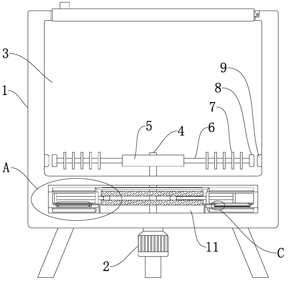
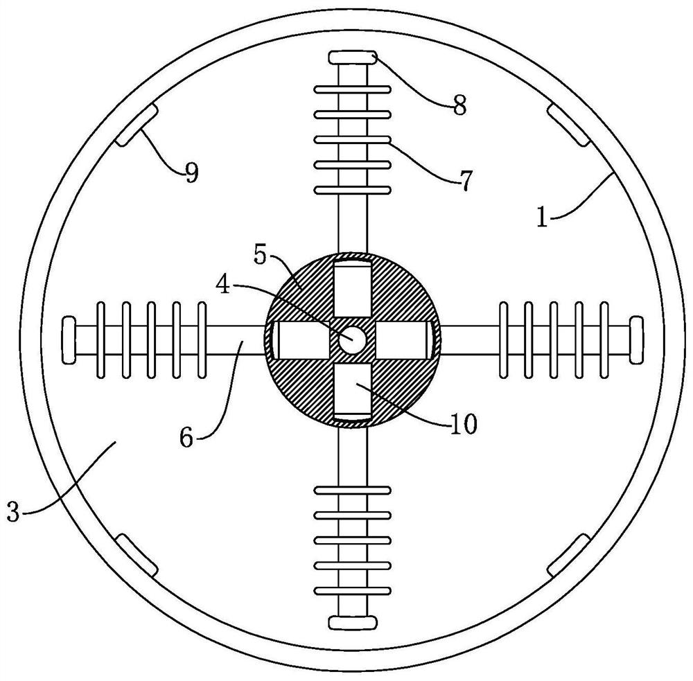
[0041] As an embodiment of the present invention, refer to figure 2 , the magnetic force assembly includes the first permanent magnets 8 that are arranged on the other ends of the plurality of slide bars 6 respectively, and the inner bottom of the dehydration chamber 3 is provided with a plurality of second permanent magnets 9 at equal intervals around the circumference, and the plurality of first permanent magnets 8 are connected to the corresponding The polarities of the opposite sides of the adjacent second permanent magnets 9 are set to be the same.

[0042] Only when the polarities of the first permanent magnet 8 and the second permanent magnet 9 close to each other are set the same, and mutual repulsion occurs between the two, the second permanent magnet 9 can be used to promote the first permanent magnet 8 to move, so that the slide bar 6 Move towards the inner bottom of the chute 10.

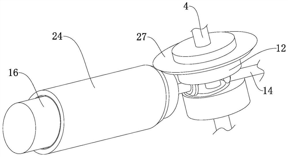
[0043] As an embodiment of the present invention, refer to Figure 3-8 , the pump...


PUM


Abstract

The invention relates to the technical field of chemical production, in particular to a chemical textile fiber dehydrator. The chemical textile fiber dehydrator comprises a machine shell, a dewatering chamber used for dehydrating textile fibers is arranged in the machine shell, a rotating mechanism used for scattering the textile fibers is arranged at the bottom of the dewatering chamber, and a device cavity is further formed in the machine shell; two cylinder bodies are symmetrically and fixedly connected to the inner walls of the two sides of the device cavity, and air pumping mechanisms which are matched with the rotating mechanism and used for spraying gas into the dewatering chamber are arranged in the two cylinder bodies; and friction mechanisms which are matched with the rotating mechanisms and are used for heating gas in the two cylinder bodies are further arranged outside the two cylinder bodies. According to the chemical fiber dehydrator, a motor drives a disc in the dewatering chamber to rotate, then drives chemical fiber raw materials in the dewatering chamber to move ceaselessly, drives compressed gas to be sprayed into the dewatering chamber and heats gas in a sliding cavity, and the dewatering rate of the materials is increased.

Description

technical field [0001] The invention relates to the technical field of chemical production, in particular to a chemical textile fiber dehydrator. Background technique [0002] Chemical fiber is a fiber with textile properties made from natural polymer compounds or artificially synthesized polymer compounds through the processes of preparation of spinning dope, spinning and post-treatment. With the further transfer of global fiber production to China, China has become the largest chemical fiber producer in the world, and China's chemical fiber production accounts for more than 60% of the world's total, and its status and role in the world's chemical fiber industry has been further enhanced; chemical fiber post-processing also includes washing, oiling, drying and other processes. [0003] Existing patent (notification number: CN203824275U) a drying device for nylon chips, including a conical tower, the conical tower includes a tower body and a tower cover, the top of the tower...

Claims


Application Information

Patent Timeline
Patent Type & Authority Applications(China)
IPC IPC(8): F26B11/14F26B21/00F26B25/04F26B25/06
CPCF26B11/14F26B21/001F26B21/004F26B25/04F26B25/06
Inventor 唐文燕汪辉
Owner 唐文燕
Why Eureka
Try Eureka