Method for improving boundary effect of metal work function

A boundary effect and work function technology, applied in the direction of electrical components, transistors, electric solid-state devices, etc., can solve the problem of 14nm FinFET threshold voltage reduction, achieve the effect of reducing the metal boundary effect and increasing the threshold voltage

Pending Publication Date: 2021-10-15
SHANGHAI HUALI INTEGRATED CIRCUTE MFG CO LTD
View PDF0 Cites 0 Cited by
  • Summary
  • Abstract
  • Description
  • Claims
  • Application Information

AI Technical Summary

Problems solved by technology

[0004] In view of the shortcomings of the prior art described above, the purpose of the present invention is to provide a method for improving the metal work function boundary effect, which is used to solve the problem in the prior art that the threshold voltage of 14nm FinFET decreases with the increase of the metal boundary effect

Method used


Image

  • Method for improving boundary effect of metal work function
  • Method for improving boundary effect of metal work function
  • Method for improving boundary effect of metal work function

Examples


Embodiment Construction

[0028] Embodiments of the present invention are described below through specific examples, and those skilled in the art can easily understand other advantages and effects of the present invention from the content disclosed in this specification. The present invention can also be implemented or applied through other different specific implementation modes, and various modifications or changes can be made to the details in this specification based on different viewpoints and applications without departing from the spirit of the present invention.

[0029] see Figure 2 to Figure 8 . It should be noted that the diagrams provided in this embodiment are only schematically illustrating the basic idea of ​​the present invention, and only the components related to the present invention are shown in the diagrams rather than the number, shape and shape of the components in actual implementation. Dimensional drawing, the type, quantity and proportion of each component can be changed arb...


PUM


Abstract

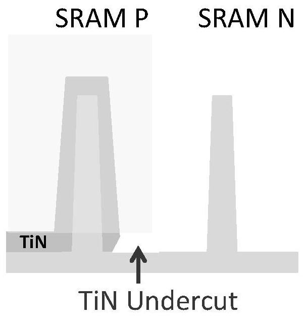
The invention provides a method for improving a metal work function boundary effect. The method comprises the steps of: depositing a first TiN layer on a first Fin structure, a second Fin structure, a third Fin structure and a fourth Fin structure; distributing the first TiN layers on the second Fin structure and the third Fin structure continuously; removing the first TiN layer on the third Fin structure; locating and pushing the edge of the removed first TiN layer at the center line of the second Fin structure and the third Fin structure towards the second Fin structure by a first distance; depositing second TiN layers, wherein the second TiN layers on the second and third Fin structures are continuously distributed; removing the second Fin structure and the second and first TiN layers on the second Fin structure; and removing the part, close to the second Fin structure, of the second TiN layer between the second Fin structure and the third Fin structure, and pushing the edge of the removed second TiN layer towards the second Fin structure by a second distance from the center line of the second Fin structure and the third Fin structure. By adopting the method provided by the invention, the thickness of the TiN layer at the edge of the bottom of the Fin structure of the P-type tube with the ultralow threshold voltage can be thinner; and during etching, the TiN layer is not easy to have a bottom cutting phenomenon, so that the metal boundary effect is reduced, and the threshold voltage of the device is increased.

Description

technical field [0001] The invention relates to the technical field of semiconductors, in particular to a method for improving the boundary effect of metal work function. Background technique [0002] The current of 14nm FinFET in the prior art is prone to metal boundary effect (MBE, Metal boundary effect), especially between the Fin of N-type SRAM and P-type SRAM, because during the manufacturing process, the Fin side of P-type SRAM is covered The bottom of the TiN will appear cut off at the bottom of the edge, such as figure 1 as shown, figure 1 It is a structural schematic diagram showing a cut-off phenomenon (TiN undercut) at the bottom of the side of the Fin structure in the prior art; and the increase of the metal boundary effect will lead to a gradual decrease in the threshold voltage of the P-type SRAM. [0003] Therefore, it is necessary to increase the threshold voltage of 14nm FinFET, and its metal boundary effect must be reduced. Contents of the invention ...

Claims


Application Information

Patent Timeline
Patent Type & Authority Applications(China)
IPC IPC(8): H01L27/11
CPCH10B10/12H01L21/32139
Inventor 翁文寅
Owner SHANGHAI HUALI INTEGRATED CIRCUTE MFG CO LTD
Why Eureka
Try Eureka