Terminal crimping machine for branching

A terminal crimping machine and branching technology, which is applied in the direction of connection, line/collector parts, electrical components, etc., can solve the problem of easy arching of the cable, and achieve the advantages of simple and labor-saving operation, good effect, and ingenious structural design Effect

Pending Publication Date: 2021-10-15
湖北永瑞电子科技股份有限公司
View PDF3 Cites 0 Cited by
  • Summary
  • Abstract
  • Description
  • Claims
  • Application Information

AI Technical Summary

Problems solved by technology

[0003] The purpose of the present invention is to solve the problem that the existing terminal crimping machine transports the cable between the upper and lower molds to be easily arched, and to provide a terminal crimping machine for branching, which can reduce the defective rate of products

Method used


Image

  • Terminal crimping machine for branching
  • Terminal crimping machine for branching
  • Terminal crimping machine for branching

Examples


Embodiment 1

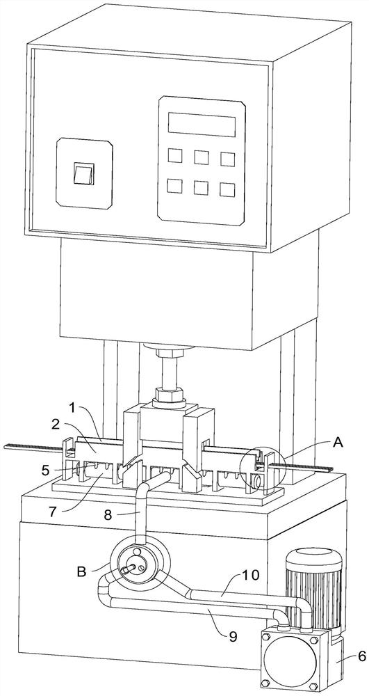
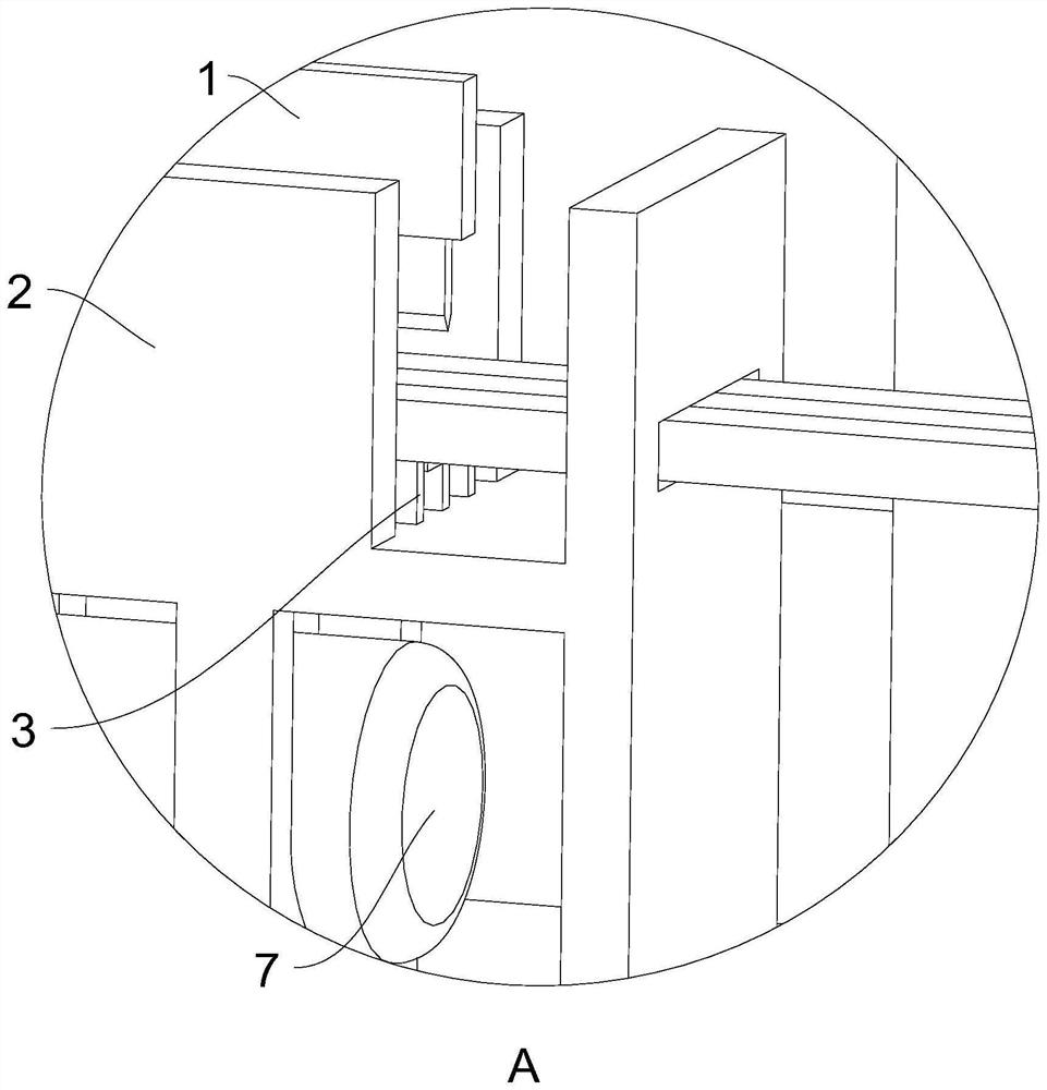
[0040] A terminal crimping machine for branching provided by the present invention, such as Figure 1 to Figure 8 As shown, the upper mold 1 and the lower mold 2 that the vertical movable pipe is arranged below the upper mold 1 are included, the longitudinal section of the lower mold 2 is U-shaped, and the opposite of the upper mold 1 and the lower mold 2 A plurality of slitting blades 3 are arranged in a staggered manner corresponding to the surface, and the lower mold 2 is uniformly provided with a plurality of air holes 4 and is connected with a plurality of branch pipes 5 communicating with the air holes 4, and also includes an air extraction device 6. The suction device 6 communicates with the branch pipe 5 .

[0041] Working process: the cable is pre-passed from the clamping mechanism on one side of the lower mold 2 to the clamping mechanism on the other side of the lower mold 2, and the two sides of the U-shaped lower mold 2 can carry out the wiring A certain degree of...

Embodiment 2

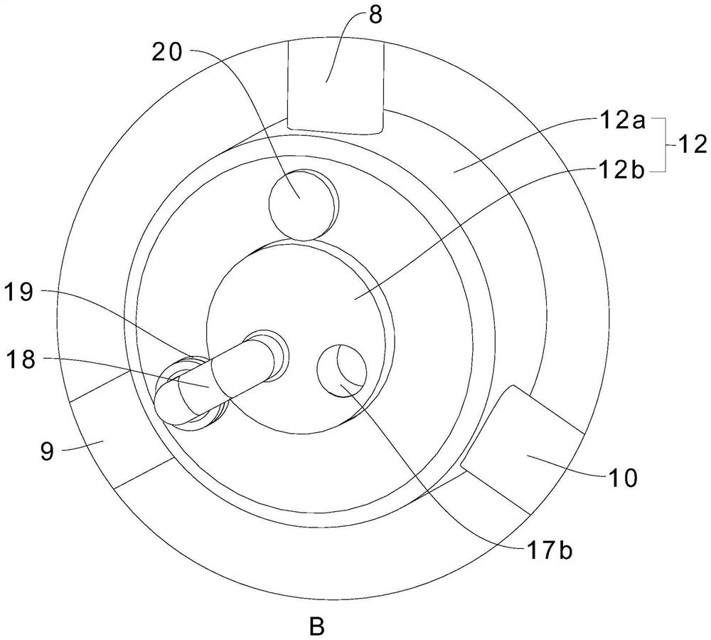
[0053] A terminal crimping machine for branching, such as Figure 9 As shown, different from the structure of the conversion assembly 12 in Embodiment 1, it also includes a first conversion tube 21 and a second conversion tube 22, and the first conversion tube 21 and the second conversion tube 22 are connected to the communication tube 8 The first conversion pipe 21 and the second conversion pipe 22 are provided with a control valve 23, the first conversion pipe 21 is screwed to the outlet pipe 10, and the second conversion pipe 22 is connected to the second conversion pipe 22. The air intake pipe 9 is threaded.

[0054]Suction function conversion: When the air suction device 6 exerts its suction function to make the cable and the lower mold 2 fit together, the first conversion pipe 21 is separated from the air outlet pipe 10, and will be installed on the first conversion pipe 21 The control valve 23 of the second conversion pipe 22 is closed, and the second conversion pipe 2...


PUM


Abstract

The invention relates to the field of terminal crimping, and discloses a terminal crimping machine for branching. The terminal crimping machine comprises an upper die and a lower die which are oppositely arranged, the upper die can perform lifting motion / can be relatively close to or far away from the lower die / the upper die can move up and down, the longitudinal section of the lower die is U-shaped, a plurality of slitting blades are correspondingly arranged on the opposite faces of the upper die and the lower die in a staggered mode, a plurality of air holes are evenly formed in the lower die, the lower die is connected with a plurality of branch pipes communicated with the air holes, and the slitting die further comprises an air extractor communicated with the branch pipes. The air holes, the branch pipes and the air extractor are arranged, the air extractor is started to form airflow during cutting, and the flat cable is attached to the lower die under the action of the airflow and is difficult to arch, so that the situation that the flat cable is obliquely cut by the cutting blade when the flat cable is arched is avoided, a good cutting effect is ensured, and the defective rate is reduced.

Description

technical field [0001] The present invention relates to the technical field of terminal crimping, in particular to a terminal crimping machine for branching lines. Background technique [0002] Terminal crimping machine is a machine widely used in wire processing. In wire processing, it is necessary to use a terminal crimping machine to intermittently cut the cable (plastic bonding) so that it can be intermittently cut into several thin wires (the inside is an independent conductive wire). A set of crimping dies is set corresponding to the terminal crimping machine. The upper and lower parts of the die are equipped with slitting blades, and the slitting blades of the upper and lower dies are arranged alternately. A strip-shaped slitting blade is set on the upper mold, and two strip-shaped slitting blades are set on the lower mold. The cable is conveyed between the upper and lower molds and clamped by the clamping mechanism set on both sides of the mold, but because the par...

Claims


Application Information

Patent Timeline
IPC IPC(8): H01R43/048
CPCH01R43/048Y02E60/10
Inventor 王超张开俊
Owner 湖北永瑞电子科技股份有限公司
Why Eureka
Try Eureka