Paper box conveying equipment with powder removing device

A technology for conveying equipment and cartons, which is applied in the field of carton conveying, which can solve problems such as dropping, affecting the cleanliness of the end face of the conveying device, and adhesion, and achieve the effect of avoiding pollution

Active Publication Date: 2021-10-19
佛山市禅城区天华印业有限公司
View PDF9 Cites 0 Cited by
  • Summary
  • Abstract
  • Description
  • Claims
  • Application Information

AI Technical Summary

Problems solved by technology

[0003] Based on the discovery of the above-mentioned inventors, the existing carton conveying equipment with a powder removal device mainly has the following disadvantages, for example: the carton needs to be cut before cutting, and the cutter does not touch the carton when cutting. Cutting produces a large amount of paper powder, which is attached to the end face of the carton. When it is conveyed through the conveying equipment, the paper powder will fall on the end face of the conveying device when it is shaken, causing the paper powder to adhere to the end face of the conveying device. Create conditions that affect the cleanliness of the end face of the conveyor

Method used


Image

  • Paper box conveying equipment with powder removing device
  • Paper box conveying equipment with powder removing device
  • Paper box conveying equipment with powder removing device

Examples


Embodiment 1

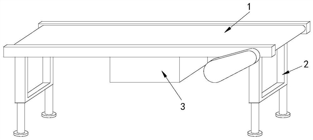
[0028] Example 1: Please refer to Figure 1-Figure 6 , the specific embodiments of the present invention are as follows:

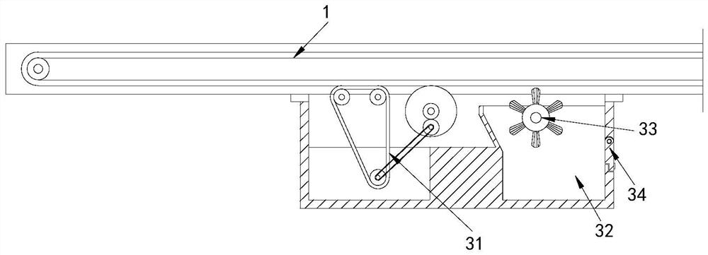
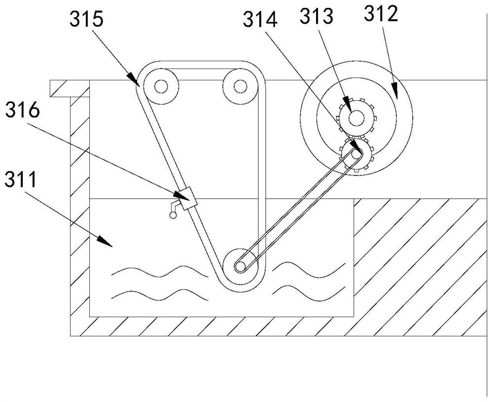
[0029] Its structure includes a conveyor belt 1, a support foot 2, and a powder removal device 3. The bottom end of the conveyor belt 1 is provided with a support foot 2, and two of the support feet 2 are arranged horizontally. The powder removal device 3 Installed in the middle of the bottom of the conveyor belt 1, the powder removal device 3 includes a cleaning device 31, a powder collection tank 32, a cleaning brush 33, and a box door 34, and the cleaning device 31 is arranged on the left side of the powder removal device 3, so The powder collecting tank 32 is located at the bottom of the right end of the powder removing device 3, the cleaning brush 33 is installed on the upper end of the powder collecting tank 32, and is attached to the end face of the conveyor belt 1, and the box door 34 is arranged at the right end of the powder collecting tank 32 ....

Embodiment 2

[0035] Example 2: Please refer to Figure 7-Figure 9 , the specific embodiments of the present invention are as follows:

[0036] The cloth topping device a6 includes a fixed seat c1, an elastic piece c2, a contact pad c3, and a return spring c4. The end surface of the fixed seat c1 is provided with two elastic pieces c2, and the end surface of the elastic piece c2 is arc-shaped. The contact pad c3 connects the ends of the two elastic sheets c2, the return spring c4 is provided with two, and is respectively embedded in the bottom end surface of the contact pad c3, the return spring c4 is movably matched with the contact pad c3, It is beneficial to drive the contact pad c3 upwards through the reset of the return spring c4.

[0037] The contact pad c3 includes an engaging seat c31, a sliding groove c32, and a buffer pad c33. The engaging seat c31 is fixed on the end surface of the contact pad c3. There are two sliding grooves c32, which are respectively arranged on the engaging...


PUM


Abstract

The invention discloses paper box conveying equipment with a powder removing device. The paper box conveying equipment structurally comprises a conveying belt, two supporting legs and the powder removing device, the two supporting legs are transversely arranged, the powder removing device is installed in the middle of the bottom of the conveying belt, and the powder removing device comprises a cleaning device, a powder collecting groove, a cleaning brush and a box door. The cleaning device comprises a cleaning pool, a friction roller, a gear set, a belt, scrubbing cloth and a water removing device, the water removing device comprises a water removing block, a fixing block, a material guide block, a rewinding spring, a water scraping device and a cloth jacking device, the water scraping device comprises a water scraping block, a water through hole and a buffer pad, and the buffer pad comprises a buffer block, a rubber ring, an empty groove and a friction block. The friction roller makes contact with the bottom of the conveying belt to rotate, then the belt drives a rotating shaft to operate, the scrubbing cloth can be attached to the end face of the conveying belt for scrubbing, paper powder attached to the end face of the conveying belt is scrubbed cleanly, and the situation that the end face of the conveying belt is polluted is avoided.

Description

technical field [0001] The invention relates to the field of carton conveying, in particular to carton conveying equipment with a powder removing device. Background technique [0002] Cartons need to be cut, creased, extruded, glued and other processes during processing, and each process needs to be connected by conveying equipment, so that the carton can be automatically transported to the next process for processing. [0003] Based on the discovery of the above-mentioned inventors, the existing carton conveying equipment with a powder removal device mainly has the following disadvantages, for example: the carton needs to be cut before cutting, and the cutter does not touch the carton when cutting. Cutting produces a large amount of paper powder, which is attached to the end face of the carton. When it is conveyed through the conveying equipment, the paper powder will fall on the end face of the conveying device when it is shaken, causing the paper powder to adhere to the e...

Claims


Application Information

Patent Timeline
Patent Type & Authority Applications(China)
IPC IPC(8): B65G45/18B65G45/10B65G45/24B65G45/22
CPCB65G45/18B65G45/10B65G45/24B65G45/22
Inventor 郑振贵
Owner 佛山市禅城区天华印业有限公司
Why Eureka
Try Eureka