
External hanging type road roller unmanned auxiliary driving system

A technology for assisting driving and road rollers, which is applied in the direction of roads, roads, road repairs, etc. It can solve the problems of less refitting applications of ordinary road rollers, high cost and time consumption, and different refitting methods, so as to achieve convenient and quick refitting, reduce work burden, The effect of improving efficiency and quality

Active Publication Date: 2021-10-19
HEBEI UNIV OF TECH
View PDF7 Cites 4 Cited by
  • Summary
  • Abstract
  • Description
  • Claims
  • Application Information

AI Technical Summary

Problems solved by technology

This technology limits the concept of unmanned driving to the unmanned road rollers produced by the manufacturers, and is not universal. In the project, more ordinary road rollers driven by ordinary drivers and repeated rolling operations in the construction area are used. In order to realize the unmanned driving function of this type of roller with the above method, it is necessary to make major changes to the oil circuit and circuit of the roller chassis, and to package the controller inside the chassis of the roller to realize unmanned control, which is costly and time-consuming, and is not applicable , and for different types of road rollers, the internal oil circuit packaging methods are different, and the modification methods are also different, so it is difficult to implement
And this kind of scheme is more applied to the design scheme of the unmanned road roller that leaves the factory, and it is less applied to the modification of ordinary road rollers

Method used


Image

  • External hanging type road roller unmanned auxiliary driving system
  • External hanging type road roller unmanned auxiliary driving system
  • External hanging type road roller unmanned auxiliary driving system

Examples


Embodiment 1

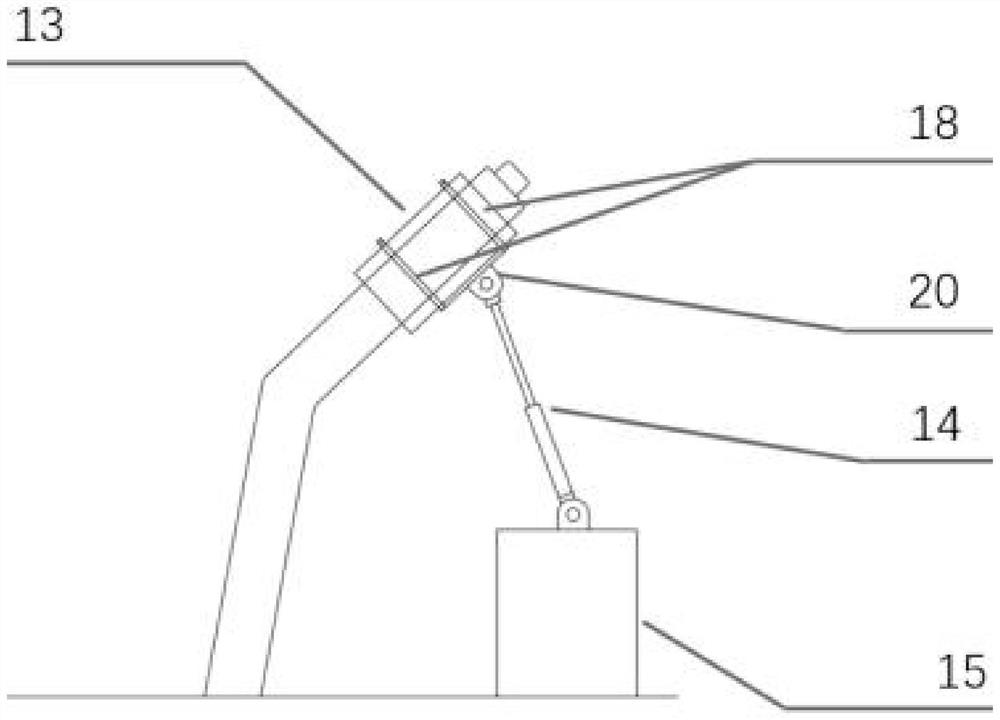
[0084] In this embodiment, the unmanned assisted driving system of the externally mounted road roller is refitted on the basis of the ordinary road roller, and a steering wheel cover and a hydraulic mechanical arm are added to the control of the steering wheel. The left and right parts of the steering wheel cover are connected by two telescopic frames. The steering wheel cover is made of rubber material so that it fits closely with the steering wheel of the road roller to prevent the steering wheel from sliding. The material of the telescopic frame 9 is iron, and the telescopic frame is fixedly connected with the steering wheel cover. Part 18 closely fits the left part of the steering wheel cover to the steering wheel through bolts, and the second fastener 19 is fixed to the first connecting part 17 by bolts on the one hand, and fixed to the part of the steering wheel cover 8 on the other hand. The first connecting part 17 At the same time, the steering hydraulic mechanical arm...


PUM


Abstract

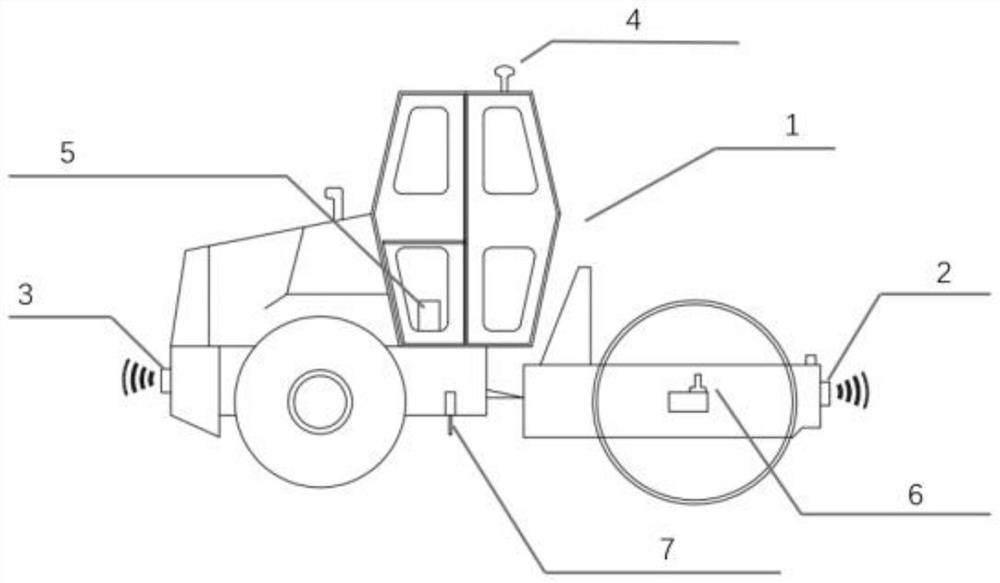
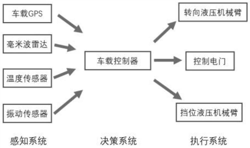
The invention relates to an external hanging type road roller unmanned auxiliary driving system, according to the auxiliary driving system, a manned road roller is modified, a vehicle-mounted GPS, a millimeter wave radar, a vibration sensor and a temperature sensor are arranged on the road roller, and the output ends of the temperature sensor, the vehicle-mounted GPS and the vibration sensor are connected with a vehicle-mounted data box; the vehicle-mounted data box is connected with an auxiliary controller; a steering wheel of the cab is connected with the steering hydraulic mechanical arm through a first transition part, and the gear position of the cab is connected with the gear hydraulic mechanical arm through a second transition part. the vehicle-mounted data box and the auxiliary controller are loaded in the case, and the auxiliary controller is electrically connected with the control switch, the steering hydraulic mechanical arm, the gear hydraulic mechanical arm, the front millimeter-wave radar and the rear millimeter-wave radar at the same time; and the control switch is connected in parallel with a vibration switch of the vibration control circuit of the manned road roller. Aiming at unmanned quick modification of a common road roller driven by a driver, unmanned driving of the common road roller is realized.

Description

technical field [0001] The invention relates to the technical field of an unmanned auxiliary driving system for an externally mounted road roller. Background technique [0002] Unmanned road rollers proposed in road construction at this stage usually control their internal oil circuit structure to achieve vibration control, travel control, steering control and braking control of the road roller. This type of unmanned road roller has its limitations, usually For the road roller manufacturer, the unmanned control system is integrated and packaged inside the chassis of the road roller, so as to realize the unmanned driving of the road roller. [0003] For example, Xia Panfu et al. (Xia Panfu, Gao Liang. Discussion on the design of unmanned road rollers [J]. Road Construction Machinery and Construction Mechanization, 2019, 36(06): 22-26.) gave an unmanned road roller In the design discussion, the electronic control hardware is preferred to the mechanical hardware in the executi...

Claims


Application Information

Patent Timeline
Patent Type & Authority Applications(China)
IPC IPC(8): E01C19/26B60R16/023
CPCE01C19/26E01C19/262B60R16/023
Inventor 王雪菲李建华李家乐
Owner HEBEI UNIV OF TECH
Learn More