Double-process electric furnace waste heat utilization system with stable steam parameters

A technology with steam parameters and two processes, applied in the field of waste heat recovery devices, can solve the problems of difficulty in stabilizing the steam inlet parameters of the turbine, limited smelting characteristics of electric furnaces, hidden dangers of pipe bursting on the heating surface, etc., to achieve stable output, reduce initial investment, and improve The effect of power generation efficiency

Pending Publication Date: 2021-10-19
上海四方无锡锅炉工程有限公司
View PDF0 Cites 0 Cited by
  • Summary
  • Abstract
  • Description
  • Claims
  • Application Information

AI Technical Summary

Problems solved by technology

[0002] The electric furnace waste heat utilization system commonly used in the market is limited by the smelting characteristics of the electric furnace, and can only produce saturated steam, and can only provide 0.8~1.0MpaG low-pressure saturated steam to the steam turbine inlet, and the actual operating flue gas temperature and flue gas The gas volume fluctuates periodically, which makes it difficult to stabilize the steam intake parameters of the turbine, resulting in low power generation efficiency
Moreover, because the first two heat exchangers of the general electric furnace waste heat utilization system are the vaporization flue and the vaporization top cover, both adopt forced circulation and need to be equipped with a circulating pump. Such a structure has the hidden danger of tube explosion on the heating surface
Another electric furnace waste heat utilization system in the prior art that can improve the efficiency of the steam turbine adopts the method of electric furnace waste heat + superheated furnace, which needs to use external energy to provide superheated steam to the steam turbine. The actual operation efficiency of this waste heat recovery system is relatively low

Method used


Image

  • Double-process electric furnace waste heat utilization system with stable steam parameters
  • Double-process electric furnace waste heat utilization system with stable steam parameters

Examples


Embodiment Construction

[0015] The present invention will be further described below in conjunction with the accompanying drawings.

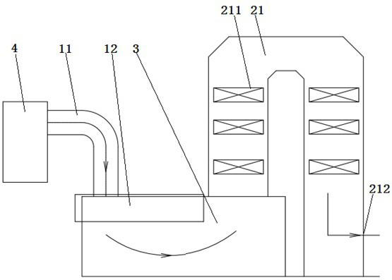
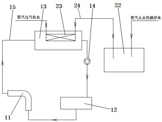
[0016] Such as figure 1 , 2 As shown, a dual-process electric furnace waste heat utilization system with stable steam parameters includes a heat transfer oil working medium process and a steam working medium process. 12 and the heat transfer oil storage tank 13 arranged on the heat transfer oil flue 11 and the heat transfer oil furnace top 12, the heat transfer oil flue 11, the heat transfer oil furnace top 12 and the heat transfer oil storage tank 13 are sequentially connected through the heat transfer oil pipe 15 to realize the heat transfer oil in the three Circulation in the structure; the steam working medium process includes a waste heat boiler 21, a heat accumulator 22 and a superheater 23 connected in sequence through a steam pipeline 24, and the superheater 23 is placed inside the heat transfer oil storage tank 13; The heat transfer oil flue 11 of the heat t...


PUM


Abstract

The invention discloses a double-process electric furnace waste heat utilization system with stable steam parameters. The double-process electric furnace waste heat utilization system comprises a heat conduction oil working medium process and a steam working medium process; the heat conduction oil working medium process comprises a heat conduction oil flue, a heat conduction oil furnace top and a heat conduction oil storage tank arranged at the upper parts of the heat conduction oil flue and the heat conduction oil furnace top, and the heat conduction oil flue, the heat conduction oil furnace top and the heat conduction oil storage tank are sequentially connected through heat conduction oil pipes to realize circulation of heat conduction oil in the three structures; the steam working medium process comprises a waste heat boiler, a heat accumulator and a superheater which are sequentially connected through a steam pipeline, and the superheater is arranged in the heat conduction oil storage tank; the heat conduction oil flue and the heat conduction oil furnace top of the heat conduction oil working medium process and the waste heat boiler of the steam working medium process are sequentially connected to form a high-temperature smoke circulation channel for waste heat recovery. The invention relates to the double-process electric furnace waste heat utilization system which has the stable steam parameters and can realizing entering of a steam turbine without the assistance of external energy.

Description

technical field [0001] The invention relates to the technical field of waste heat recovery devices, in particular to a double-flow electric furnace waste heat utilization system with stable steam parameters. Background technique [0002] The electric furnace waste heat utilization system commonly used in the market is limited by the smelting characteristics of the electric furnace, and can only produce saturated steam, and can only provide 0.8~1.0MpaG low-pressure saturated steam to the steam turbine inlet, and the actual operating flue gas temperature and flue gas The gas volume fluctuates periodically, which makes it difficult to stabilize the steam intake parameters of the turbine, resulting in low power generation efficiency. Moreover, because the first two heat exchangers of the general electric furnace waste heat utilization system are the vaporization flue and the vaporization top cover, both of which adopt forced circulation and need to be equipped with a circulation...

Claims


Application Information

Patent Timeline
Patent Type & Authority Applications(China)
IPC IPC(8): F27D17/00F22B1/18F22G1/02
CPCF27D17/004F22B1/18F22G1/02Y02P10/25
Inventor 陆晓伟
Owner 上海四方无锡锅炉工程有限公司
Why Eureka
Try Eureka