

Equipment vibration abnormity diagnosis method and system
A technology for abnormal diagnosis and equipment, applied in character and pattern recognition, instrument, pattern recognition in signals, etc., can solve the problems of measurement equipment damage, interference, economic loss, etc., to ensure robustness, improve accuracy and reliability reliability effect
- Summary
- Abstract
- Description
- Claims
- Application Information
AI Technical Summary
Problems solved by technology
Method used
Image

Examples
Embodiment Construction
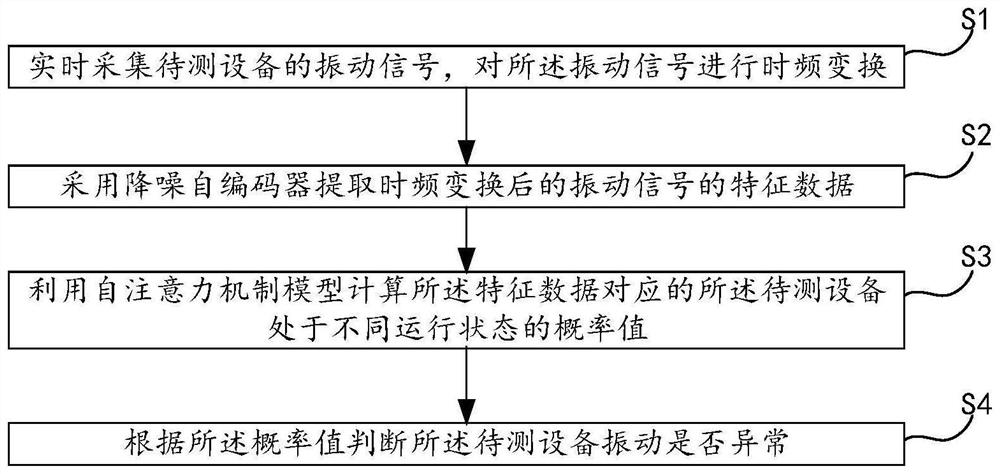
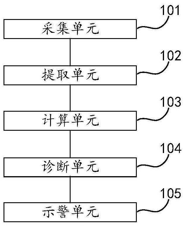
[0035] In order to make the purpose, technical solutions and advantages of the present disclosure clearer, the present disclosure will be further described in detail below in conjunction with the accompanying drawings and embodiments. It should be understood that the specific embodiments described here are only used to explain the present disclosure, not to limit the present disclosure.
[0036] In the description of the present invention, reference to the terms "one embodiment," "some embodiments," "exemplary embodiments," "examples," "specific examples," or "some examples" is intended to mean that the embodiments are A specific feature, structure, material, or characteristic described by or example is included in at least one embodiment or example of the present invention. In this specification, schematic representations of the above terms do not necessarily refer to the same embodiment or example. Furthermore, the specific features, structures, materials or characteristics...
PUM
 Abstract
Description
Claims
Application Information