Beam forming method and system for optimizing main and side lobe ratio

A technology of beamforming and main-sidelobe, which is applied in the field of communication, can solve problems such as low sidelobe levels, and achieve the effect of reducing computational complexity and improving efficiency

Inactive Publication Date: 2021-10-19
ANHUI POLYTECHNIC UNIV MECHANICAL & ELECTRICAL COLLEGE
View PDF0 Cites 0 Cited by
  • Summary
  • Abstract
  • Description
  • Claims
  • Application Information

AI Technical Summary

Problems solved by technology

In most static beamforming, the optimal main-side lobe ratio is an ideal criterion that engineers continue to pursue. At present, the main optimization methods include conventional amplitude weighting (such as Taylor weight, Hamming weight, etc.), genetic algorithm, particle swarm algorithm, cuckoo Bird search algorithm, etc. Although these existing algorithms can obtain lower sidelobe levels, they cannot theoretically prove that the main-sidelobe ratio of the synthetic beam pattern is optimal

Method used


Image

  • Beam forming method and system for optimizing main and side lobe ratio
  • Beam forming method and system for optimizing main and side lobe ratio
  • Beam forming method and system for optimizing main and side lobe ratio

Examples


Embodiment Construction

[0050] Specific embodiments of the present invention will be described in detail below in conjunction with the accompanying drawings. It should be understood that the specific embodiments described here are only used to illustrate and explain the present invention, and are not intended to limit the present invention.

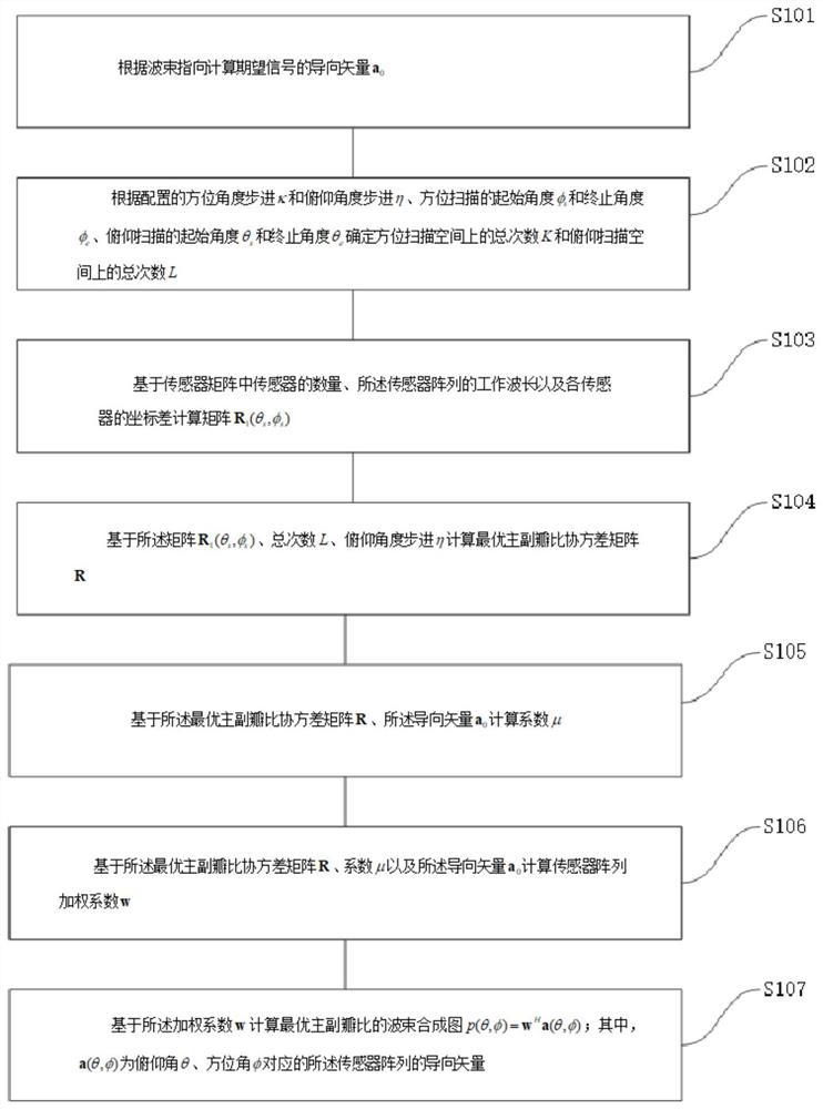
[0051] figure 1 is a flow chart of a beamforming method for optimizing the main-sidelobe ratio provided by the present invention, such as figure 1 As shown, the beamforming method for optimizing the main-side lobe ratio includes:

[0052] S101, according to the incident azimuth angle φ of the desired signal 0 and pitch angle θ 0 Calculate the steering vector a of the desired signal 0 ;

[0053] S102, according to the configured azimuth angle step κ and pitch angle step η, the starting angle φ of the azimuth scan s and termination angle φ e , the starting angle θ of pitch scanning s and the termination angle θ e Determine the total number of times K on t...


PUM


Abstract

The invention discloses a beam forming method and system for optimizing a main-side lobe ratio. The beam forming method for optimizing the main-side lobe ratio comprises the following steps: calculating a steering vector a0 of a desired signal according to an incident azimuth angle and a pitch angle of the desired signal; according to the configured azimuth angle step kappa and pitch angle step eta, the initial angle [phi]s and the termination angle [phi]e of azimuth scanning, and the initial angle [theta]s and the termination angle [theta]e of pitch scanning, determining the total number K of times in the azimuth scanning space and the total number L of times in the pitch scanning space; calculating a matrix R1 ([theta]s, [phi]s) based on the number of the sensors in the sensor matrix, the working wavelength of the sensor array and the coordinate difference of each sensor: calculating a beam synthesis graph p (theta, phi) = wHa (theta, phi) of the optimal main and side lobe ratio based on the weighting coefficient w, wherein a (theta, phi) is a steering vector of the sensor array corresponding to the pitch angle theta and the azimuth angle phi. According to the method, the array weighting coefficient is calculated under the constraint condition of the incident azimuth angle and the pitch angle of the expected signal, so the sensor array beam pattern with the optimal main and side lobe ratio is formed.

Description

technical field [0001] The present invention relates to the field of communication technology, in particular to a beam forming method and system for optimizing the main-side lobe ratio. Background technique [0002] In modern signal transmission systems such as radar, sonar, AM / FM, satellite broadcasting, cellular phone, GPS and wireless local area network, there are four kinds of diversity techniques used to improve signal quality and reduce interference: time diversity, frequency diversity, code Meta-diversity and space diversity. Spatial diversity is achieved by using the geometry of multiple sensors (such as antennas) in an array. The physical design of the array can form a beam of specific orientation, so that no energy is radiated / received in a specific angle range in space, and the radiation / reception of the maximum energy is achieved at a specified angle, which is the so-called array beamforming. [0003] Since World War II, the design of antenna arrays has been ex...

Claims


Application Information

Patent Timeline
Patent Type & Authority Applications(China)
IPC IPC(8): H04B7/06H04B7/08
CPCH04B7/0617H04B7/086
Inventor 刘春静张天飞
Owner ANHUI POLYTECHNIC UNIV MECHANICAL & ELECTRICAL COLLEGE
Why Eureka
Try Eureka