Novel electrolysis structure device for wastewater treatment

A new type of wastewater treatment technology, applied in water/sewage treatment, water/sewage treatment equipment, water/sewage multi-stage treatment, etc., can solve the problems of dead corners of wastewater, low work efficiency, no collection structure, etc., to reduce resources waste, improve work efficiency, and reduce the effect of excess space

Inactive Publication Date: 2021-10-22
南通市金宏电化设备有限公司
View PDF10 Cites 3 Cited by
  • Summary
  • Abstract
  • Description
  • Claims
  • Application Information

AI Technical Summary

Problems solved by technology

", but the flow field of the device is poor in actual use, there is a certain dead angle in the electrolysis of wastewater, and it is difficult for the wastewater to pass through the electromagnetic field, so that its working efficiency is low;
[0005] 2. The comparative document CN205635003U discloses a pulse electrolysis wastewater treatment device, "The electrolysis machine includes an upper cylinder and a lower cylinder, the lower end of the upper cylinder is provided with a grid support, the upper end is provided with a partition, and the partition is provided with an overflow plate , the positive plate and the negative plate in the upper cylinder between the separator and the overflow plate are arranged at intervals, and the electrolytic carrier filler is arranged between the positive and negative plates, and the inner cavity of the regulating cylinder communicates with the inner cavity of the lower cylinder of the first-stage electrolyzer , the inner cavity of the lower cylinder of the next-stage electrolyzer communicates with the chamber above the partition plate of the upper cylinder body of the previous-stage electrolyzer, and the chamber side wall above the partition plate of the upper cylinder body of the last-stage electrolyzer is set There is a discharge joint, and the high-pressure aeration pipe is respectively connected to the bottom of the adjustment cylinder and the lower cylinder of the electrolysis machine, and an aeration head is installed. The bottom of the electrolysis machine is equipped with a sewage discharge joint. Wastewater treatment by pulse electrolysis method", but the overall volume of the device is relatively large, and it needs to occupy a large area in actual use. It is time-consuming and labor-intensive for the staff to use, and it does not have a certain novelty;
In this treatment device, by designing a reactor with a multi-stage reaction chamber, the average particle size of the iron-carbon filler in the reactor decreases sequentially, so that the organic wastewater can be filtered layer by layer, and micro-electrolysis occurs with the iron-carbon filler in the reaction chamber. Reaction, as the particle size of the iron-carbon filler decreases, the specific surface junction gradually increases, which can treat a variety of different concentrations of organic wastewater, especially high-concentration organic wastewater, which is initially filtered and micro-electrolyzed at the bottom layer, and then flows into the upper layer In-depth filtration and micro-electrolysis have the advantages of continuous high efficiency and no hardening. While greatly removing organic pollutants, it improves the biodegradability of organic wastewater and lays a good foundation for subsequent biological treatment.” However, the device Without a more convenient collection structure, the solid pollutants produced during the electrolysis of wastewater are difficult to be cleaned up quickly, thus affecting the quality of work

Method used


Image

  • Novel electrolysis structure device for wastewater treatment
  • Novel electrolysis structure device for wastewater treatment
  • Novel electrolysis structure device for wastewater treatment

Examples


Embodiment 1

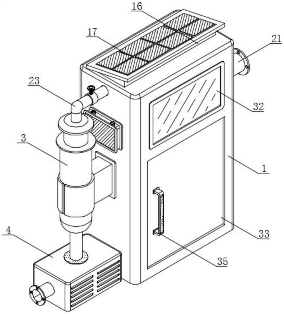
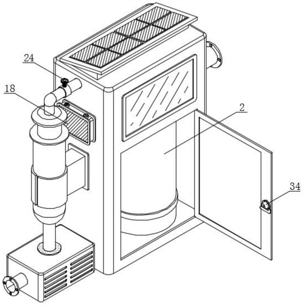
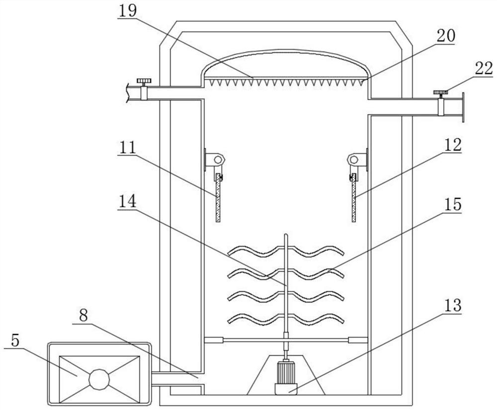
[0043] see figure 1 , figure 2 , image 3 with Image 6 , an embodiment provided by the present invention: a novel electrolytic structural device for wastewater treatment, comprising a work box 1, a treatment tank 2 and a purification tank 3, the inside of the work box 1 is provided with a treatment tank 2, and a part of the work box 1 The side is provided with a purification tank 3; the bottom of one side of the working box 1 is provided with a storage box 4, and the inside of the storage box 4 is provided with a water pump 5; Fixed clip 7 is arranged, and purification tank 3 is positioned at the inside of fixed clip 7, and the bottom of processing tank 2 surface is provided with water inlet pipe 8, and the top of water inlet pipe 8 is connected to the output end of water pump 5, and the inner side wall of processing tank 2 is installed with The connecting plate, the surface of the connecting plate is equipped with a fixed rod 9, the top of the fixed rod 9 is connected wi...

Embodiment 2

[0046] see figure 1 , figure 2 with Figure 4 , an embodiment provided by the present invention: a novel electrolytic structural device for wastewater treatment, comprising a work box 1, a support block 16 is installed on the top of the work box 1, a solar panel 17 is installed on the top of the support block 16, and the work box One side of 1 is provided with a battery box 18, and the inside of the solar panel 17 is electrically connected to the battery box 18, and the battery box 18 is located above the fixed block 6;

[0047] Through the setting of the working box 1, when the staff needs to reduce the occupied area of ​​the device, the collocation of the fixing block 6, the fixing clip 7 and the purification tank 3 can effectively reduce the redundant space of the device by adopting an integrated connection method. , the supporting block 16, the solar panel 17 and the battery box 18 work together, and the inside of the solar panel 17 is electrically connected to the batt...

Embodiment 3

[0049] see image 3 , an embodiment provided by the present invention: a novel electrolytic structural device for wastewater treatment, including crushing teeth 20 and an air outlet pipe 21, a limiting plate 19 is installed on the top of the treatment tank 2, and several A crushing tooth 20, the top of the treatment tank 2 side is provided with an air outlet pipe 21, and the surface of the air outlet pipe 21 is provided with a sealing valve 22;

[0050] Through the setting of the crushing teeth 20 and the air outlet pipe 21, when the staff needs to deal with the air bubbles that appear during electrolysis, the limit plate 19 and the crushing teeth 20 work together, and the crushing teeth 20 can puncture larger air bubbles, thereby The device can better control the generated air bubbles, and the collocation of the air outlet pipe 21 and the sealing valve 22 can make the inside of the device maintain a good seal, thereby making the reaction in the treatment tank 2 more sufficien...


PUM


Abstract

The invention discloses a novel electrolysis structure device for wastewater treatment. The device comprises a work box, a treatment tank and a purification tank, the treatment tank is arranged in the work box, and the purification tank is arranged on one side of the work box; a placement box is arranged at the bottom of one side of the working box, and a water pump is arranged in the placement box; and a fixing block is mounted in the middle of one side of the work box. Through the arrangement of the treatment tank and the matched work of the water inlet pipe, the water pump and the treatment tank, wastewater can enter from the lower part and exit from the upper part and can be forced to flow, so that the situation that the wastewater is difficult to completely pass through a magnetic field is avoided. A fixed rod and fixed teeth work together to support a positive electrode plate and an auxiliary electrode plate. After the device is connected to a power supply, the positive electrode plate and the auxiliary electrode plate are matched to work to electrolyze the wastewater, and a driving motor, a movable rod and stirring blades work together to improve the activity of the wastewater in the treatment tank, so that the structure can better electrolyze the wastewater.

Description

technical field [0001] The invention relates to the technical field of wastewater treatment, in particular to a novel electrolytic structure device for wastewater treatment. Background technique [0002] Micro-electrolysis technology is an ideal process for treating high-concentration organic wastewater. It is also called internal electrolysis. The potential difference electrolytically treats the wastewater, so as to achieve the purpose of degrading organic pollutants. [0003] A kind of existing defective that is used for wastewater treatment novel electrolytic structure device exists is: [0004] 1. The comparative document CN210656286U discloses a waste water micro-electrolysis device, "comprising a bottom plate, an outer shell is arranged at the middle position of the top of the bottom plate, an inner shell is arranged inside the outer shell, and an inner shell is arranged between the outer shell and the inner shell. Vacuum layer, one side of the top of the bottom plat...

Claims


Application Information

Patent Timeline
Patent Type & Authority Applications(China)
IPC IPC(8): C02F1/461C02F9/06B01F7/18C02F101/30
CPCC02F1/46104C02F1/001C02F2101/30C02F2201/46105
Inventor 张英志
Owner 南通市金宏电化设备有限公司
Why Eureka
Try Eureka