A nitrogen removal device for denitration wastewater and ammonia nitrogen wastewater

A technology for ammonia nitrogen wastewater and wastewater, applied in water/sewage treatment, multi-stage water/sewage treatment, neutralized water/sewage treatment, etc., can solve problems such as economic loss, low mixing efficiency, and inability to improve the efficiency of ammonia nitrogen removal. Improve consumption speed and cost, avoid forward and backward displacement, and improve nitrogen removal efficiency

Active Publication Date: 2022-03-01
HEBEI GEO UNIVERSITY
View PDF24 Cites 0 Cited by
  • Summary
  • Abstract
  • Description
  • Claims
  • Application Information

AI Technical Summary

Problems solved by technology

[0003] Most users add phosphate to denitrification wastewater and ammonia nitrogen wastewater to form struvite while quickly removing ammonia nitrogen. However, when mixing wastewater with phosphate, the mixing efficiency is low, and the wastewater cannot be mixed within a certain period of time. Complete mixing reaction with phosphate, too long mixing time will not improve the efficiency of ammonia nitrogen removal, will only greatly increase the consumption speed and cost of energy, and will bring great economic losses to users. Therefore, those skilled in the art provide A nitrogen removal device for denitrification wastewater and ammonia nitrogen wastewater is developed to solve the problems raised in the above-mentioned background technology

Method used


Image

  • A nitrogen removal device for denitration wastewater and ammonia nitrogen wastewater
  • A nitrogen removal device for denitration wastewater and ammonia nitrogen wastewater
  • A nitrogen removal device for denitration wastewater and ammonia nitrogen wastewater

Examples


Embodiment

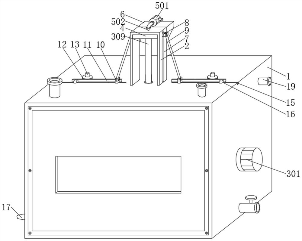
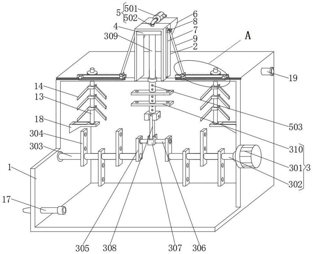
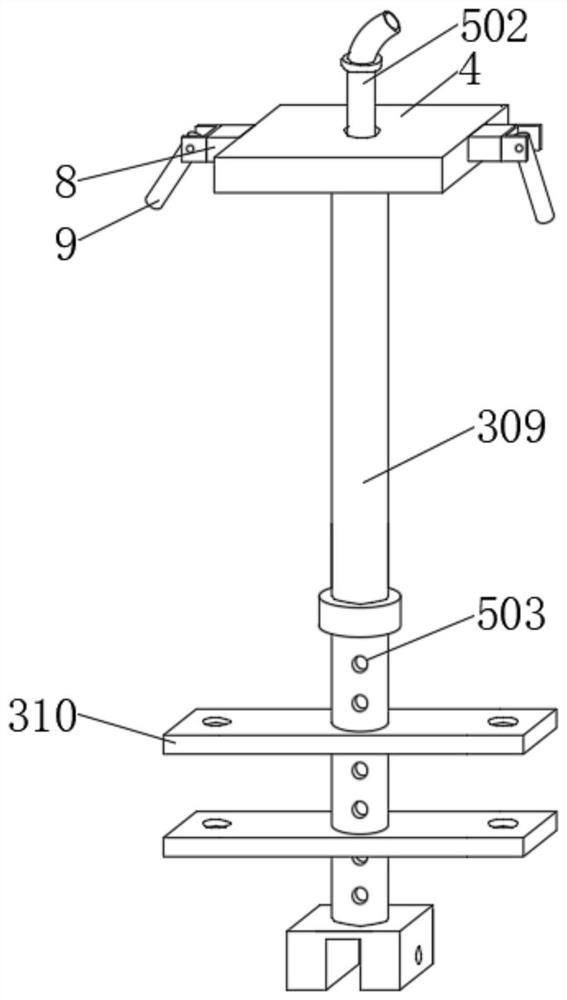
[0036] The following is attached Figure 1-7 The present invention is described in further detail.

[0037] A nitrogen removal device for denitrification wastewater and ammonia nitrogen wastewater, comprising a treatment box 1, the top of the back of the right side of the treatment box 1 is provided with a heating pipe 19, and the heating pipe 19 can use external heating equipment to heat the inside of the treatment box 1, so that the treatment The temperature in the box 1 is always kept at 25°C to 30°C, so as to avoid the effect of the temperature being too high or too low on the nitrogen removal efficiency of the device for wastewater. Mechanism 3, the fixed frame 2 is provided with the jet mechanism 5 used in conjunction with the rapid mixing mechanism 3, the front of the processing box 1 top is connected with the feeding pipe and the medicine feeding pipe successively from left to right, the back side of the fixed frame 2 is provided with The support seat 6 used in conjunct...


PUM


Abstract

The invention discloses a nitrogen removal device for denitrification wastewater and ammonia nitrogen wastewater, comprising a treatment box, the top of the treatment box is fixedly connected with a fixing frame, and a fast mixing mechanism is arranged in the treatment box, and the fixing frame is provided with The air injection mechanism used in conjunction with the rapid mixing mechanism, the front of the top of the treatment box is connected with a feeding pipe and a medicine feeding pipe in sequence from left to right. The invention sets up a fast mixing mechanism and uses the motor as the driving source to drive the stirring rod to rotate. At this time, with the assistance of the auxiliary shaft, the two sets of mounting plates can be driven synchronously to drive the rotating shaft to rotate, and the stirring rod and the auxiliary shaft are synchronized. Drive the first stirring blade to rotate quickly and mix the solution in the treatment box quickly, so that with the help of the fixed sleeve, the driving plate is driven to pull the fixed tube to continuously reciprocate up and down, and then the second stirring blade is continuously moved up and down and the processing The solution in the box is quickly mixed and stirred for the second time.

Description

technical field [0001] The invention belongs to the technical field of wastewater treatment, and more specifically relates to a nitrogen removal device for denitration wastewater and ammonia nitrogen wastewater. Background technique [0002] When thermal power plants use flue gas technology, there will be a large amount of wastewater. At the same time, the wastewater will contain a lot of ammonia nitrogen and other heavy metal impurities. Users need to treat the wastewater in time to avoid excessive discharge of ammonia nitrogen that will cause irreversible harm to the surrounding waters. . [0003] Most users add phosphate to denitrification wastewater and ammonia nitrogen wastewater to form struvite while quickly removing ammonia nitrogen. However, when mixing wastewater with phosphate, the mixing efficiency is low, and the wastewater cannot be mixed within a certain period of time. Complete mixing reaction with phosphate, too long mixing time will not improve the efficie...

Claims


Application Information

Patent Timeline
Patent Type & Authority Patents(China)
IPC IPC(8): C02F9/04C02F1/58B01F31/44B01F27/70B01F27/191B01F33/40C02F101/16
CPCC02F1/586C02F1/66C02F2101/16C02F2201/002
Inventor 赵楠段亚敏
Owner HEBEI GEO UNIVERSITY
Why Eureka
Try Eureka