
System and method for optically positioning and measuring level of liquid in transparent container

A transparent container, optical positioning technology, applied in measurement devices, liquid/fluid solid measurement, instruments, etc., can solve the problems of practical impact, no technical solution, too general refraction and reflection in the crescent-shaped area, etc. Small sampling time interval, improve measurement accuracy, and improve the effect of measurement repeatability

Pending Publication Date: 2021-10-22
夏荆
View PDF1 Cites 1 Cited by
  • Summary
  • Abstract
  • Description
  • Claims
  • Application Information

AI Technical Summary

Problems solved by technology

[0008] 1. Due to the comprehensive positioning of the liquid level by using the interactive relationship between the photoelectric and optical values ​​of two pairs of infrared emitting and receiving tubes, the distance between the infrared emitting axes and the influence of the diameter difference of the glass tube on the measurement results are not considered, so the distance between the axes and the diameter of the tube cannot be eliminated. to the measurement error;
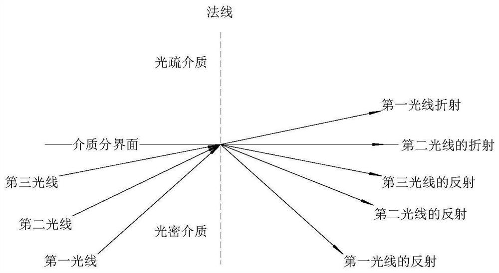
[0009] 2. Since this method is not clear about the relationship between the two pairs of infrared emission and reception photoelectric light values ​​and different positions of the liquid surface, the concave liquid surface is simply regarded as a crescent shape, and the refraction and reflection of the crescent-shaped area with light is too general
[0010] 3. Since this method finds a point where the intersection of two simulation curves is used as the liquid level location, it is reasoned that the relative height difference between this point and the actual measurement point can be corrected through system calibration to achieve the purpose of accurate liquid level positioning, so how to find A better liquid level positioning method to obtain a theoretically correct reference value is the key to system calibration, but this method does not give a corresponding technical solution, so that the key technical solution is not determined. The practicality of the method is somewhat affected by

Method used


Image

  • System and method for optically positioning and measuring level of liquid in transparent container
  • System and method for optically positioning and measuring level of liquid in transparent container
  • System and method for optically positioning and measuring level of liquid in transparent container

Examples


Embodiment 1

[0111] Embodiment 1 is to apply the present invention to the positioning and measurement of the liquid level height in a single liquid level pipe.

[0112] The transparent container in embodiment 1 is that single liquid level tube is glass tube 13; Single liquid level tube is glass tube 13; And in order to verify the actual technical effect of the present invention, embodiment 1 was repeated three times, each time using different The glass tube 13; the final experimental results are shown in Table 1.

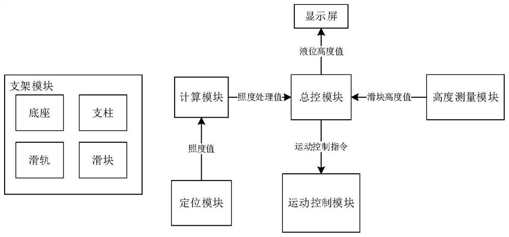
[0113] Such as Image 6 As shown, a system for optically locating and measuring the liquid level in a transparent container consists of the following modules:

[0114] Bracket module: including base 2, pillar, slide rail 4 and slider 3; the pillar is vertically and fixedly installed on the upper surface of the base 2; the slide rail 4 is detachably connected to the pillar, and is on the same side of the base 2 as the pillar; the slide rail 4 The extension direction of the base...

Embodiment 2

[0170] Embodiment 2 is to specifically apply the present invention to liquid level positioning and liquid level height difference measurement in double liquid level pipes.

[0171] The transparent container in Embodiment 2 is a U-shaped glass tube 15 .

[0172] It needs to be explained in advance that the basic principle of optical positioning liquid pressure gauge measurement is to measure the height difference between the two liquid levels, and the pressure difference between the two liquid levels can be calculated and measured by the formula: P=ρ·g·h.

[0173] Such as Figure 7 , Figure 8 with Figure 9 As shown, a system for optically locating and measuring the liquid level in a transparent container consists of the following modules:

[0174] Bracket module: including base 2, pillar, slide rail 4 and slider 3; the pillar is vertically and fixedly installed on the upper surface of the base 2; the slide rail 4 is detachably connected to the pillar, and is on the same si...


PUM


Abstract

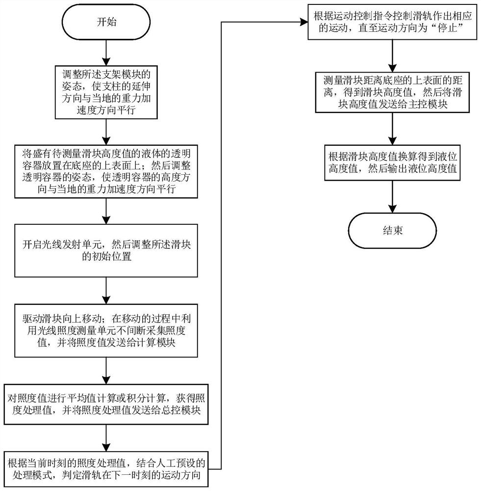
The invention relates to a liquid level positioning system in an optical non-contact transparent container. The liquid level positioning system comprises a support module; a master control module which receives an illumination processing value, judges the movement direction of a sliding rail, receives the height value of a sliding block and converts the height value into a liquid level height value; a motion control module which receives a motion control instruction and controls the sliding rail to move; a positioning module which is used for transmitting and receiving light and measuring an illumination value; a calculation module which receives the illumination value, and carries out average value or integral calculation to obtain an illumination processing value; and a height measuring module which measures the height value of the sliding block. The invention also relates to a positioning method, which comprises the following steps of: starting a light emitting unit; driving the sliding block to move upwards; uninterruptedly acquiring an illumination value; performing average value calculation or integral calculation to obtain an illumination processing value; judging the movement direction of the sliding rail; controlling the sliding rail to move until the sliding rail is stopped; measuring the height value of the sliding block; and converting the height value into a liquid level height value. The method is higher in measurement precision; and the liquid level critical position can be greatly approached.

Description

technical field [0001] The invention relates to the technical field of precise positioning and measurement of the liquid level of a transparent liquid, in particular to a system and method for positioning the liquid level in an optical non-contact transparent container. Background technique [0002] Liquid level measurement is a widely used technology. Simply put, it is to measure the liquid level of the liquid in the container; the technical difficulty lies in the precise positioning and measurement of the liquid level, which is due to the liquid in the container due to infiltration or non-infiltration. Rising or falling along the container wall, such as the phenomenon that the edge of water rises along the wall in a glass bottle is infiltration, and the phenomenon that the edge of a mercury column descends along the wall in a glass tube is non-wetting. In a transparent tube, the liquid levels of water and mercury will therefore exhibit approximately spherical meniscus or c...

Claims


Application Information

Patent Timeline
Patent Type & Authority Applications(China)
IPC IPC(8): G01F23/00
Inventor 张英夏羽余行朱萌萌夏荆
Owner 夏荆
Learn More