
A kind of power battery test equipment and test method

A technology of power battery and test equipment, which is used in environmental/reliability testing, measuring electricity, measuring devices, etc., can solve the influence of heat generation, the refrigeration system cannot guarantee the consistency of the temperature field, and affects the test results and test efficiency of power batteries, etc. problems, to ensure consistency, improve accuracy and test efficiency, and reduce test energy consumption

Active Publication Date: 2021-12-28
JIANGSU TUOMILUO ENVIRONMENTAL TEST EQUIP CO LTD
View PDF8 Cites 0 Cited by
  • Summary
  • Abstract
  • Description
  • Claims
  • Application Information

AI Technical Summary

Problems solved by technology

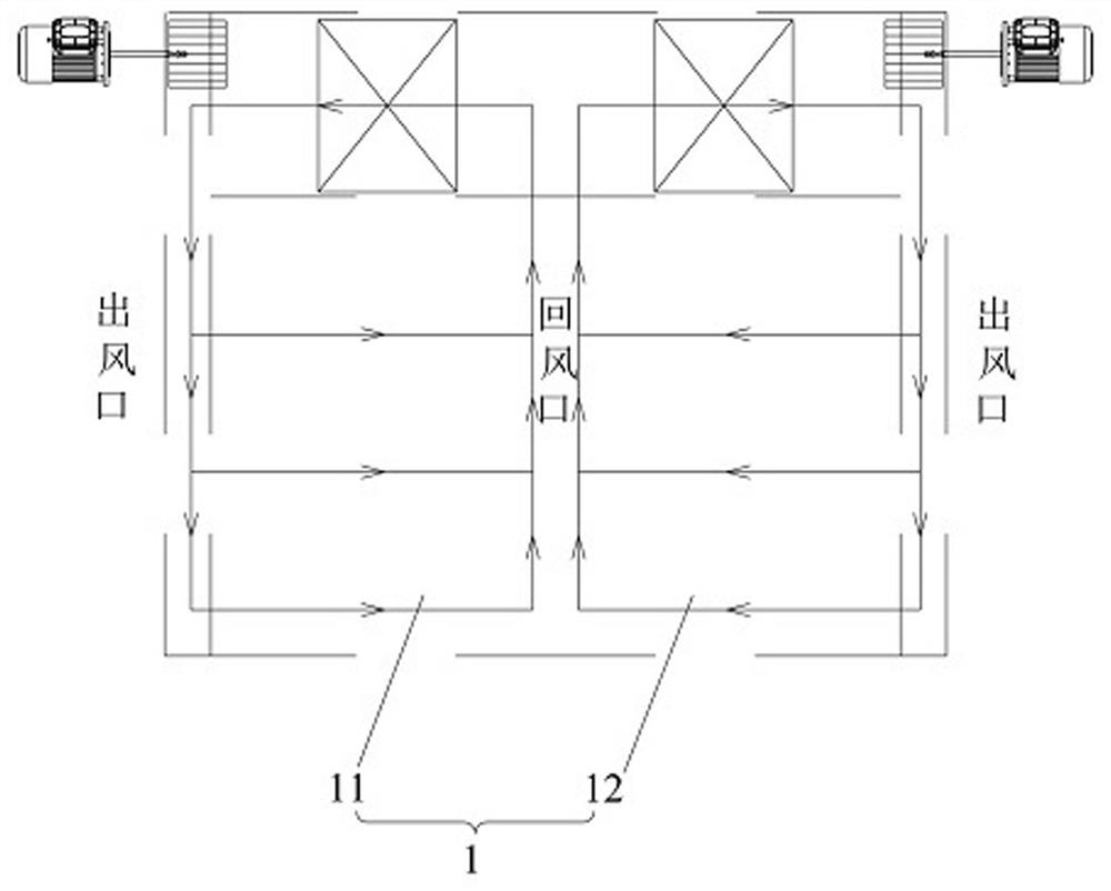
[0003] The environmental test of the power battery is generally arranged in multiple layers. The upper layer of the commonly used test air duct (vertical air duct structure, patio air supply structure) will affect the lower wind field, especially when the product has heat generation. The horizontal air duct (left air outlet and right return air) is also affected by the size of the test product. The temperature difference between the windward side and the leeward side of the product is large. When the product generates heat, the heat generated by the product on the left will affect the right.
Because the battery will be charged and discharged during the test process, it will generate a certain amount of heat, and the customer puts a lot of products. So many products are tested in the same environmental chamber. The cooling system in the existing environmental chamber cannot guarantee the temperature provided. The consistency of the field makes it impossible to guarantee the consistency of each product test, which affects the power battery test results and test efficiency

Method used


Image

  • A kind of power battery test equipment and test method
  • A kind of power battery test equipment and test method

Examples


Embodiment Construction

[0032] In order to make the technical problems solved by the present invention, the technical solutions adopted and the technical effects achieved clearer, the technical solutions of the embodiments of the present invention will be further described in detail below in conjunction with the accompanying drawings. Obviously, the described embodiments are only the technical solutions of the present invention. Some, but not all, embodiments. Based on the embodiments of the present invention, all other embodiments obtained by those skilled in the art without creative efforts fall within the protection scope of the present invention.

[0033] In the description of the present invention, it should be noted that the terms "center", "upper", "lower", "left", "right", "vertical", "horizontal", "inner", "outer" etc. The indicated orientation or positional relationship is based on the orientation or positional relationship shown in the drawings, and is only for the convenience of describin...


PUM


Abstract

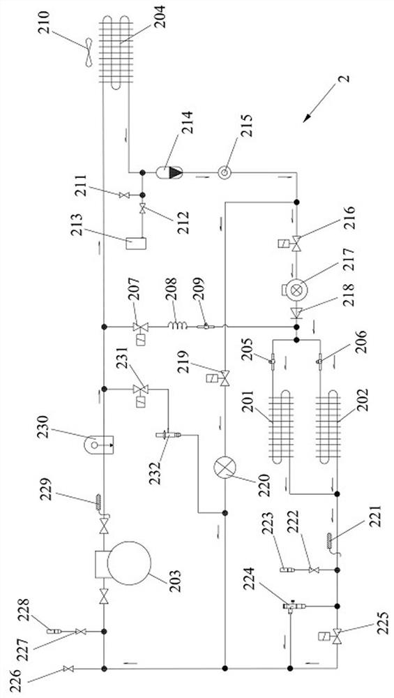
The invention relates to the field of testing equipment, and discloses a power battery testing equipment and a testing method. The power battery testing equipment includes a test air duct and a refrigeration system. The test air duct is used to simulate the test environment of the power battery to be tested. The test air duct includes a first circulating air duct and a second air circulation duct with independent air outlets and a common return air outlet. The cooling system includes a first evaporator and a second evaporator arranged in parallel, the first evaporator is used to exchange heat with the first circulating air channel, and the second evaporator is used to exchange heat with the second circulating air channel. When the temperature of the air outlet of the first circulating air duct and the second circulating air duct are inconsistent, adjust the heat exchange of the first evaporator and the second evaporator to make the temperature of the air outlet of the first circulating air duct and the second circulating air duct consistent . The invention can ensure the consistency of the provided temperature field, ensure the consistency of each product test, effectively reduce the test energy consumption, and improve the accuracy and test efficiency of the test result of the power battery.

Description

technical field [0001] The invention relates to the field of testing equipment, in particular to a power battery testing equipment and a testing method. Background technique [0002] At present, the performance tests of power batteries are completed by using high and low temperature environmental chambers that can simulate the environmental conditions of -40°C to 150°C. The air ducts generally used in the high and low temperature environmental chambers on the market are vertical air duct structure and patio air supply structure. Or horizontal air duct structure. The high and low temperature environmental chambers with vertical air duct structure and patio air supply structure are mostly used in third-party inspection agencies, consumer electronics, photovoltaic industries, etc. This structure is not widely used in environmental test chambers in the power battery industry. With the rapid development of the new energy vehicle industry, the demand for battery testing is increa...

Claims


Application Information

Patent Timeline
Patent Type & Authority Patents(China)
IPC IPC(8): G01R31/385
CPCG01R31/385G01R31/003Y02E60/10
Inventor 陈盼盼
Owner JIANGSU TUOMILUO ENVIRONMENTAL TEST EQUIP CO LTD
Learn More