Printed circuit board positioning assembly

A printed circuit board and positioning component technology, which is applied in the direction of printed circuit, printed circuit manufacturing, electrical components, etc., can solve the trouble of laying heat transfer paper, the size of printed circuit board is not the same, the feeling of laying is different, etc., to achieve fast The effect of positioning, improving efficiency, and precise positioning

Active Publication Date: 2021-10-22
深圳市恒讯通电子有限公司
View PDF12 Cites 2 Cited by
  • Summary
  • Abstract
  • Description
  • Claims
  • Application Information

AI Technical Summary

Problems solved by technology

[0002] Printed circuit boards, also known as PCB boards, are providers of electrical connections for electronic components. In the processing of printed circuit boards, it is usually necessary to etch the printed circuit board. Lines will adhere to the printed circuit board after etching, which is for subsequent The soldering process provides convenience, but it is usually necessary to manu

Method used


Image

  • Printed circuit board positioning assembly
  • Printed circuit board positioning assembly
  • Printed circuit board positioning assembly

Examples


Embodiment 1

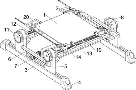
[0036] A printed circuit board positioning assembly includes placement means, such as figure 1 , figure 2 and Figure 4 As shown, the placement device includes a slide block 14, a positioning rod 15, an insulating ring 16 and an insulating pad 17, the slide block 14 is installed on the worm screw 12 and the slide rod 19, and the slide block 14 has a screw thread and a light hole, which are respectively connected to the worm screw 12 and the slide rod 19. The slide bar 19 is corresponding, so that the slide block 14 can move back and forth with the rotation of the worm screw 12, the positioning rod 15 and the insulating pad 17 are fixed above the slide block 14, and the diameter of the positioning rod 15 is smaller than the diameter of the positioning hole 2 on the printed circuit board 1, And the upper end is provided with a chamfer, so that the printed circuit board 1 can be inserted better, the insulating ring 16 is sleeved on the positioning rod 15, and is used to place t...

Embodiment 2

[0038] Embodiment 2: The difference from Embodiment 1 is that when the printed circuit board 1 is a special-shaped board, the printed circuit board 1 cannot be fixed and positioned by the four corners, so the slider 14 can be adjusted so that the positioning rod 15 is aligned with the positioning hole on the printed circuit board 1 2, the positioning hole 2 on the printed circuit board 1 can be set in the positioning rod 15, so that the printed circuit board 1 is placed on the insulating ring 16, and the printed circuit board 1 is fixed and positioned, which is convenient for pasting the thermal transfer paper.

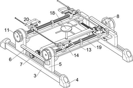
[0039] A printed circuit board positioning assembly includes a lifting device, such as figure 2 As shown, the lifting device is composed of a tray 18, which is fixed on the second mounting plate 10. The upper surface of the tray 18 is 2 mm higher than the placement plane of the placement device, so that the placement device will not bump into the printed circuit board...


PUM


Abstract

The invention aims to provide a printed circuit board positioning assembly, which: comprises a left-right adjusting device comprising a sliding rail, a first mounting plate, a rack, a gear and a first servo motor and capable of performing left-right positioning on a printed circuit board; a front-back adjusting device comprising a second servo motor, a worm rod, a third mounting plate and a sliding rod and capable of positioning the printed circuit board front and back; a placing device comprising a sliding block, a positioning rod, an insulating ring and an insulating pad and used for placing the printed circuit board; and a lifting device composed of a tray and capable of carrying out center lifting on the printed circuit board with the four corners positioned so as to prevent the phenomenon that the middle of the large printed circuit board is sunken, and a pressing rod can press and fix the printed circuit board after heat transfer printing paper is laid so as to facilitate production of the printed circuit board.

Description

technical field [0001] The invention relates to the field of printed circuit boards, in particular to a printed circuit board positioning component. Background technique [0002] Printed circuit boards, also known as PCB boards, are providers of electrical connections for electronic components. In the processing of printed circuit boards, it is usually necessary to etch the printed circuit board. Lines will adhere to the printed circuit board after etching, which is for subsequent The soldering process provides convenience, but it is usually necessary to manually lay the thermal transfer paper on the printed circuit board in the etching of the printed circuit board, because the printed circuit board is usually placed directly on the workbench without a fixed position, and the printed circuit board The size of the board is not the same, and the feeling of laying is also different, so it brings a lot of trouble when laying the heat transfer paper. Contents of the invention ...

Claims


Application Information

Patent Timeline
IPC IPC(8): H05K3/00H05K3/06
CPCH05K3/00H05K3/06H05K2203/15H05K2203/0165
Inventor 李全荣廖桂花李剑波
Owner 深圳市恒讯通电子有限公司
Why Eureka
Try Eureka