Aerator for generating aerated liquid stream
A technology of jet regulator and liquid jet, which is applied in indoor sanitary pipeline installations, buildings, water supply installations, etc., can solve problems such as leakage, and achieve the effect of reducing the risk of leakage
- Summary
- Abstract
- Description
- Claims
- Application Information
AI Technical Summary
Problems solved by technology
Method used
Image

Examples
Embodiment Construction
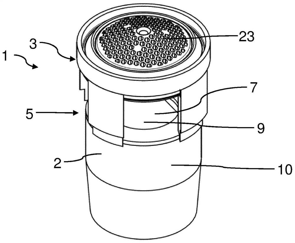
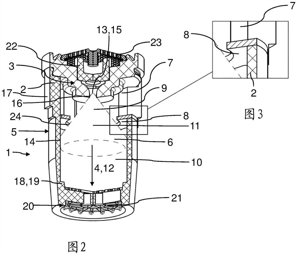
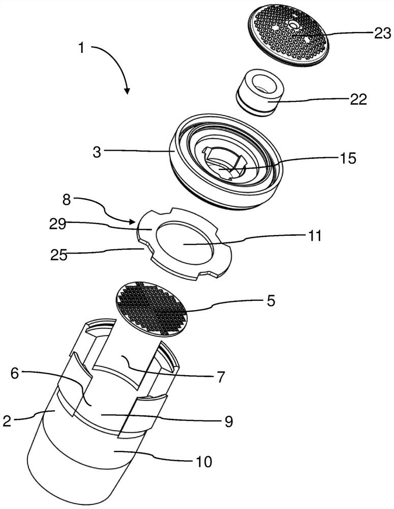
[0036] exist figure 1 , 2 , 4, 5, 6, 8 and 9 show three embodiments of the jet regulator, generally designated 1 . The jet regulator 1 is provided for generating an aerated liquid jet.
[0037] The jet regulator 1 has a housing 2 via which the jet regulator 1 can be connected to a jet regulator receptacle of a sanitary fitting. For this purpose, a coupling point can be formed on the outside of the housing 2 , which can be connected to a corresponding mating coupling point of the sanitary outlet fitting.
[0038] A jet acceleration device 3 is arranged or formed inside the housing 2 . The jet acceleration device 3 is provided to break up the jet flowing into the jet acceleration device 3 into a plurality of separate liquid fractions.
[0039]A screen 23 can be arranged on the inflow side upstream of the jet acceleration device 3 .
[0040] A jet aeration device 5 is provided downstream of the jet acceleration device 3 in the flow direction 4 (of the liquid flowing through ...
PUM
 Abstract
Description
Claims
Application Information
PatSnap Eureka turns technology decisions into work you can execute. Powered by our Innovation Knowledge Graph, it runs expert workflows across engineering, life sciences, materials and intellectual property. Get your review-ready output in minutes.


