Metal part polishing device

A technology for metal parts and fixing devices, which is applied in the field of metal parts grinding devices, can solve the problems of inability to maintain the pressure between metal parts and sandpaper, affect the grinding effect, and low grinding efficiency, and achieve convenient fixing of sandpaper, high grinding efficiency, installation and disassembly convenient effect

Active Publication Date: 2021-10-26
金爵五金塑胶(深圳)有限公司
View PDF6 Cites 2 Cited by
  • Summary
  • Abstract
  • Description
  • Claims
  • Application Information

AI Technical Summary

Problems solved by technology

[0004] Aiming at the deficiencies of the prior art, the present invention provides a grinding device for metal parts, which solves the problem that sandpapers of different sizes need to be frequently replaced during the grinding process of the current metal parts, and the grinding device needs to be shut down and then replaced during the replacement, so that the grinding efficiency is improved. Low, and during the grinding process, due to the gap between the metal parts and the sandpaper after wear, the pressure between the metal parts and the sandpaper cannot be kept constant, which affects the grinding effect

Method used


Image

  • Metal part polishing device
  • Metal part polishing device
  • Metal part polishing device

Examples


Embodiment 1

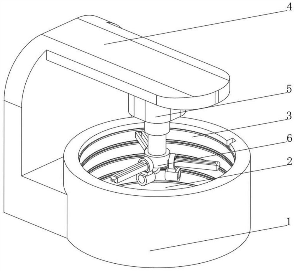
[0039] see Figure 1-2 , the present invention provides a technical solution: a metal piece grinding device, specifically comprising:

[0040] A fixed base 1, the top of the fixed base 1 is provided with a grinding groove 2, and a fixing device 3 arranged inside the grinding groove 2, and the fixing device 3 is slidingly connected with the inner wall of the grinding groove 2;

[0041] A support frame 4, the support frame 4 is arranged on one side of the fixed base 1, the top of the support frame 4 is fixedly connected with a driving device 5, and the bottom of the driving device 5 is connected with a polishing device 6 through a telescopic rod;

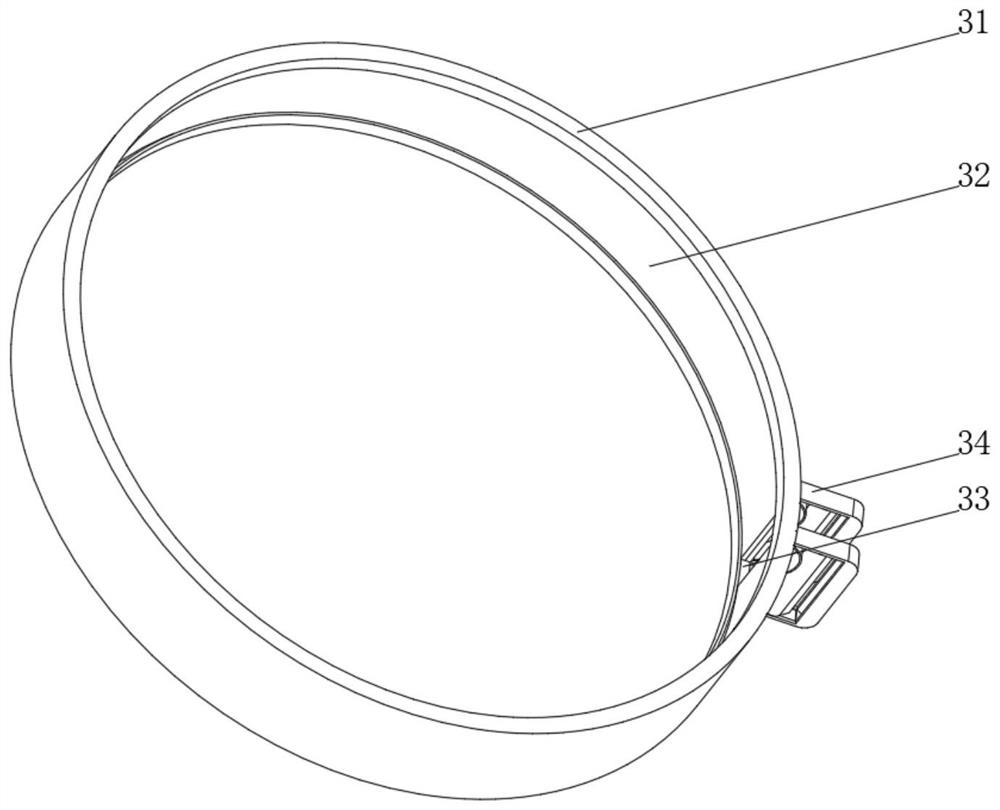
[0042] Fixture 3 includes:

[0043] Fixed ring 31, the inner wall of the fixed ring 31 is provided with a limit slideway 32, one side of the fixed ring 31 is provided with an entrance 33, both sides of the entrance 33 are provided with a clamping device 34, and the top of the limit slideway 32 inner wall side is provided with a tilti...

Embodiment 2

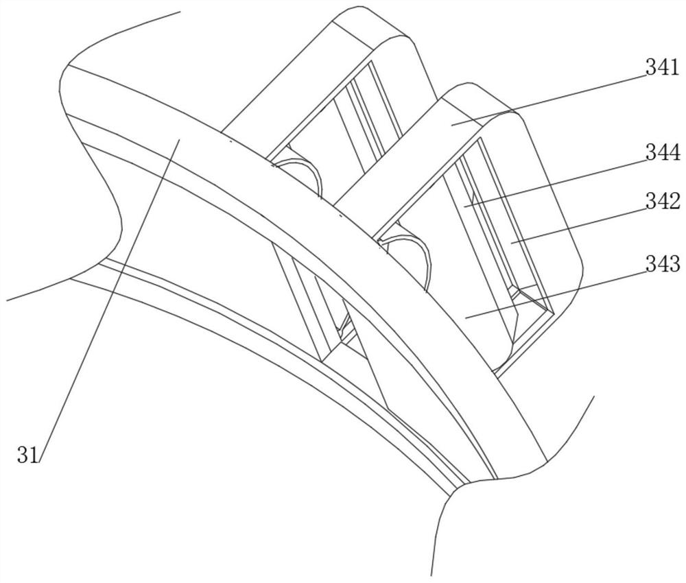
[0046] see Figure 1-3 , on the basis of Embodiment 1, the present invention provides a technical solution: the inner wall of the grinding tank 2 is provided with a chute compatible with the clamping device 34, and the clamping device 34 includes:

[0047] The fixed frame 341, one side of the fixed frame 341 is fixed on the side of the entrance 33 on the fixed ring 31, and the inner wall side of the fixed frame 341 is provided with a clamping groove 342;

[0048] Clamping rod 343, one side of the clamping rod 343 is fixedly connected to one side of the inner wall of the fixed frame 341 through an arc spring, and the side of the clamping rod 343 away from the arc spring is provided with a clamping groove 342 suitable for clamping. Block 344.

[0049] Both the bottom and the bottom of the inner wall of the fixing frame 341 are provided with limiting grooves compatible with the clamping rod 343, and both ends of the clamping rod 343 extend to the inside of the limiting groove an...

Embodiment 3

[0052] see Figure 1-4 , on the basis of Embodiment 1 and Embodiment 2, the present invention provides a technical solution: the grinding device 6 includes a fixed disc 61, and the side of the fixed disc 61 is fixedly connected with a slide bar 62, and the slide bar 62 is provided with a chute 63 for fixing The disk 61 is sleeved and slidably connected with a rotating device 64, the bottom of the rotating device 64 is fixedly connected with a clamp 65, the top of the fixed disk 61 is fixedly connected with the telescopic rod at the bottom of the driving device 5, and the sliding rods 62 are arranged in three groups and evenly distributed on the fixed disk. 61 sides.

[0053] When the grinding device 6 rotates, the fixed disk 61 drives the slide bar 62 to rotate, and the slide bar 62 drives the metal parts on the clamp 65 to rotate through the rotating device 64. One end slides, and at the same time drives the metal parts inside the fixture 65 to be compressed on the sandpaper...


PUM


Abstract

The invention discloses a metal part polishing device which specifically comprises a fixing base of which the top of is provided with a polishing groove, a fixing device which is arranged in the polishing groove and is in sliding connection with the inner wall of the polishing groove, and a supporting frame arranged on one side of the fixing base, wherein the top of the supporting frame is fixedly connected with a driving device, and the bottom of the driving device is connected with a polishing device through a telescopic rod; and the fixing device comprises a fixing ring, a limiting sliding way is formed in the inner wall of the fixing ring, an inlet is formed in one side of the fixing ring, clamping devices are arranged on the two sides of the inlet, and an inclined chamfer is formed in the top of the side face of the inner wall of the limiting sliding way. The invention relates to the technical field of machining. According to the metal part polishing device, the machine does not need to stop for replacement of abrasive paper, the polishing efficiency is high, maintenance is convenient, the pressing force between a metal part and the abrasive paper can be kept constant, the stable polishing effect can be conveniently guaranteed, and the metal part is convenient to mount and dismount.

Description

technical field [0001] The invention relates to the technical field of mechanical processing, in particular to a grinding device for metal parts. Background technique [0002] Machining refers to the process of changing the shape or performance of a workpiece through a mechanical device. According to the differences in processing methods, it can be divided into cutting processing and pressure processing. The machines required for processing include digital display milling machines, digital display forming grinders, digital display lathes, EDM machines, universal grinders, machining centers, laser welding, wire walking, Fast wire, slow wire, cylindrical grinder, internal grinder, precision lathe, etc., can be used for turning, milling, planing, grinding and other processing of precision parts. This type of machine is good at turning, milling, planing, grinding and other processing of precision parts , can process various irregular shape parts. At present, sandpaper of diffe...

Claims


Application Information

Patent Timeline
Patent Type & Authority Applications(China)
IPC IPC(8): B24B19/00B24B41/06B24B41/02B24B41/00
CPCB24B19/00B24B41/06B24B41/02B24B41/00Y02P70/10
Inventor 潘鹏
Owner 金爵五金塑胶(深圳)有限公司
Why Eureka
Try Eureka