
Detection method used for manipulator handover and detection device

A detection method and a detection device technology, which are applied in the field of manipulators, can solve problems such as reducing production efficiency, prolonging downtime, and occurrence of wear, and achieve the effects of improving production efficiency, improving solution speed, and shortening downtime

Active Publication Date: 2021-10-26
SHANGHAI MICRO ELECTRONICS EQUIP (GRP) CO LTD
View PDF15 Cites 0 Cited by
  • Summary
  • Abstract
  • Description
  • Claims
  • Application Information

AI Technical Summary

Problems solved by technology

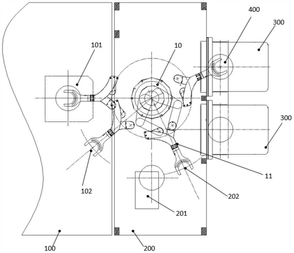
Since the manipulator 10 is driven by various shaft system motion mechanisms such as synchronous belts, lead screws, bearings, etc., wear and tear will inevitably occur after long-term use, which will affect the transmission accuracy of the manipulator 10, resulting in failure of the transfer of the silicon wafer 400, collision or It is the phenomenon that the placement position of the workpiece table station 101 exceeds the alignment field of view, etc., hereinafter collectively referred to as the silicon wafer 400 handover failure
Furthermore, since the workpiece table station 101 is fixed on the whole machine frame 100, the manipulator 10 is arranged on the silicon wafer transmission frame 200 (the sheet warehouse station 300 and the pre-alignment station 201 are also arranged on the silicon wafer transmission frame 200). frame 200), after working for a long time, if the position of the workpiece table station 101 changes, or the relative drift occurs between the silicon wafer transmission frame 200 and the whole machine frame 100, even if the transmission accuracy of the manipulator 10 itself is guaranteed , still cannot avoid the problem of silicon wafer 400 handover failure
[0003] When the failure of silicon wafer 400 handover occurs, the reason may involve multiple equipment, which undoubtedly increases the difficulty and complexity of maintenance, prolongs downtime, and reduces production efficiency

Method used


Image

  • Detection method used for manipulator handover and detection device
  • Detection method used for manipulator handover and detection device
  • Detection method used for manipulator handover and detection device

Examples


Embodiment Construction

[0044] In order to make the purpose, technical solutions and advantages of the embodiments of the present invention clearer, the technical solutions in the embodiments of the present invention will be clearly and completely described below in conjunction with the drawings in the embodiments of the present invention. Obviously, the described embodiments It is a part of embodiments of the present invention, but not all embodiments. The components of the embodiments of the invention generally described and illustrated in the figures herein may be arranged and designed in a variety of different configurations.

[0045]Accordingly, the following detailed description of the embodiments of the invention provided in the accompanying drawings is not intended to limit the scope of the claimed invention, but merely represents selected embodiments of the invention. Based on the embodiments of the present invention, all other embodiments obtained by persons of ordinary skill in the art wit...


PUM


Abstract

The invention discloses a detection method used for manipulator handover and a detection device. The detection method comprises the steps that a manipulator is moved to a first detection station on a silicon wafer conveying frame for multiple times, a first error among positions of multiple times is obtained, and if the first error is larger than a preset value, the manipulator is adjusted or replaced; after the manipulator works for a period of time, the manipulator is moved to the first detection station for multiple times, a second error among positions measured for multiple times is obtained, and if the second error is larger than the preset value, it is judged that the manipulator drifts, and the position of the manipulator at each station is corrected; and the manipulator is moved to a second detection station on a complete machine frame for multiple times, a third error among the positions measured for multiple times is obtained, and if the third error is larger than the preset value, it is judged that relative drift exists between the silicon wafer conveying frame and the complete machine frame. The detection method and the detection device contribute to comprehensively and efficiently solving the problem of silicon wafer handover failures of the manipulator.

Description

technical field [0001] The invention relates to the technical field of manipulators, in particular to a detection method and a detection device for manipulator handover. Background technique [0002] For the silicon wafer transfer system of the lithography equipment, the manipulator 10 is used as the main execution component, and is mainly responsible for transferring silicon wafers between the warehouse station 300 , the pre-alignment station 201 and the workpiece table 101 . refer to figure 1 , the manipulator 10 takes out the silicon wafer 400 from the chip warehouse station 300, first places it on the pre-alignment station 201, calibrates the placement position of the silicon wafer 400, and then the manipulator 10 transfers the placed silicon wafer 400 to the workpiece Work station 101 is on. Since the manipulator 10 is driven by various shaft system motion mechanisms such as synchronous belts, lead screws, bearings, etc., wear and tear will inevitably occur after long...

Claims


Application Information

Patent Timeline
IPC IPC(8): B65G47/52B65G47/90B65G43/00
CPCB65G47/52B65G47/90B65G43/00
Inventor 刘凯胡松立王刚
Owner SHANGHAI MICRO ELECTRONICS EQUIP (GRP) CO LTD
Learn More