Corrugated pipe valve

A bellows and valve technology, applied in the direction of sliding valve, valve details, valve device, etc., can solve the problems of poor sealing effect, cracking in welding, leakage, etc., and achieve the effect of solving easy cracking, improving strength and increasing area

Active Publication Date: 2021-10-26
NANTONG SHIFA SHIP MACHINERY
View PDF9 Cites 1 Cited by
  • Summary
  • Abstract
  • Description
  • Claims
  • Application Information

AI Technical Summary

Problems solved by technology

However, the existing bellows valves have the following problems: one is that the bellows is sleeved outside the valve stem, and the two ends are respectively connected to the valve stem and the valve cover by welding. During welding, welding can only be performed radially from the interface of the bellows. The fluid pressure inside the valve and the pressure of the valve on the bellows when the valve is opened will pass through the weld, causing the weld to crack, resulting in rupture and leakage; the second is that the valve stem and the packing will slide, and the sealing effect is not good

Method used


Image

  • Corrugated pipe valve
  • Corrugated pipe valve
  • Corrugated pipe valve

Examples


Embodiment Construction

[0032] The present invention will be further described below in conjunction with the accompanying drawings and specific embodiments.

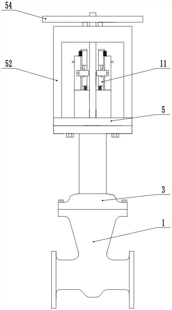
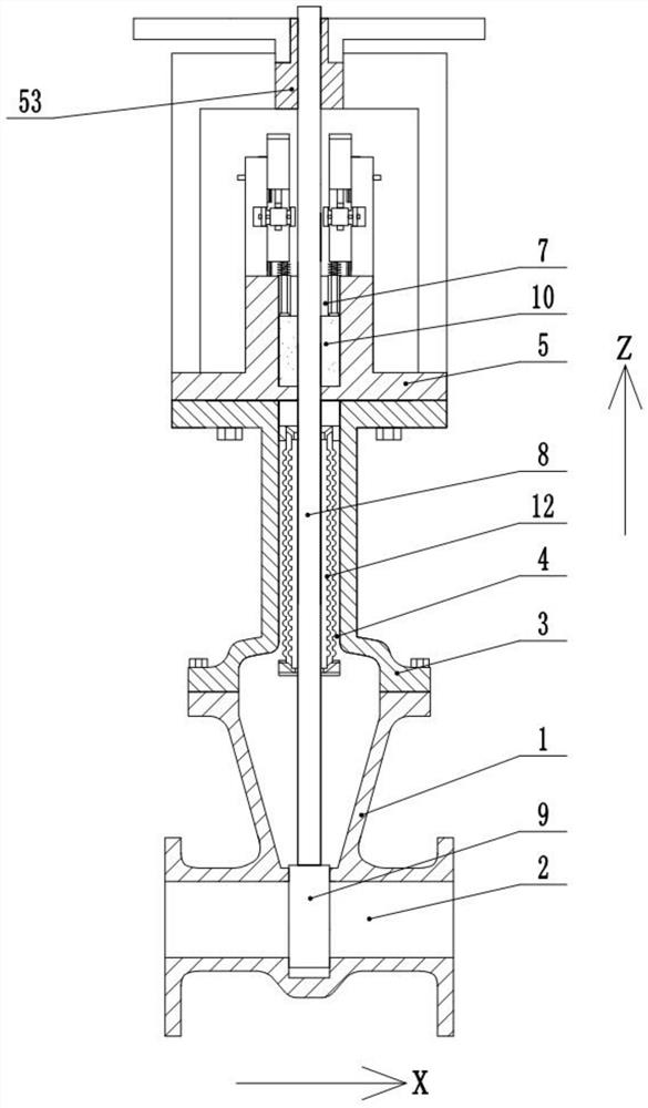
[0033] A bellows valve, including a valve body 1 with a flow chamber 2 inside, the flow chamber 2 is parallel to the X direction, and a bonnet 3 installed on the top of the valve body 1 through bolts, and the bonnet 3 is provided with a valve that communicates with the flow chamber 2 The central hole A4 is installed on the sealing cover 5 on the top of the valve cover 3 through bolts. The sealing cover 5 is provided with a central hole B communicating with the central hole A4. The top of the sealing cover 5 is provided with a central hole C7 communicating with the central hole B. The valve stem 8 passing through the center hole A4, the center hole B, and the center hole C7 is installed on the bottom of the valve stem 8 and is located in the flow cavity 2, and the valve core 9 for closing or opening the flow cavity 2 is located in the center hole...


PUM


Abstract

The invention discloses a corrugated pipe valve. The corrugated pipe valve comprises a pair of adjusting devices which are installed at the top of a sealing cover, located in a supporting frame and used for pressing filler, wherein the adjusting devices are located on the left side and the right side of a valve rod correspondingly and are in bilateral symmetry about the valve rod, the lower ends of the adjusting devices are installed on the valve rod, the upper ends of the adjusting devices are installed on the sealing cover, the corrugated pipe assembly is located in the valve cover, through the arrangement of an auxiliary ring A, an auxiliary ring B, a guide inclined plane A and a guide inclined plane B, the area of the corrugated pipe connector is increased, the heat capacity is improved, the welding area is increased, the strength of the corrugated pipe connector is improved, meanwhile, a first corrugated pipe and a second corrugated pipe are used for bearing pressure together, and the pressure bearing capacity is greatly improved; the problems that an existing filler is prone to sliding, and the sealing effect of a valve rod is poor are solved through the adjusting device; and a wedge block structure is formed among a translation frame, rollers, a translation block A and a translation block B, an adjustment rod is rotated to drive the translation block A and the translation block B to move downwards, and the pressing rod and the pressing plate press the filler downwards.

Description

technical field [0001] In particular, the invention relates to a bellows valve. Background technique [0002] With the rapid development of modern industries such as chemical industry and nuclear industry, there are more and more pipelines with flammable, explosive, highly toxic and radioactive media. The valves used in these pipelines and devices have special and strict requirements for their leakage and sealing. , the use of general packing sealing device can no longer meet the requirements, so it is necessary to adopt the valve stem sealing structure with bellows. [0003] The bellows valve is to install an extra layer of protective film in the sealing element, which can expand and contract with the opening and closing of the valve stem. It not only improves energy efficiency, increases the safety of production equipment, reduces maintenance costs and frequent maintenance, but also provides a clean and safe working environment. However, the existing bellows valves have ...

Claims


Application Information

Patent Timeline
Patent Type & Authority Applications(China)
IPC IPC(8): F16K3/02F16K3/314F16K27/04F16K27/08F16K41/10
CPCF16K3/0218F16K3/314F16K27/044F16K27/08F16K41/10
Inventor 蒋宇峰余祖耀
Owner NANTONG SHIFA SHIP MACHINERY
Why Eureka
Try Eureka