
Online hydraulic ash removal system of waste incineration waste heat boiler

A waste heat boiler and waste incineration technology, applied in the direction of incinerator, combustion method, combustion type, etc., can solve the problems of poor cleaning efficiency and insufficient cleaning, and achieve the effect of fast purging speed, short time and high effect

Pending Publication Date: 2021-10-26
CHINA TIANYING +2
View PDF1 Cites 0 Cited by
  • Summary
  • Abstract
  • Description
  • Claims
  • Application Information

AI Technical Summary

Problems solved by technology

However, the spray gun angle control system determines the soot-blowing trajectory of the water sprayed onto the water-cooled wall. Because there are intermediate partitions in the second and third flues of waste incineration waste heat boilers, this method tends to have dead angles that cannot be cleaned, and the cleaning efficiency is poor. , and the installation location will also be limited by the space of the water wall

Method used


Image

  • Online hydraulic ash removal system of waste incineration waste heat boiler
  • Online hydraulic ash removal system of waste incineration waste heat boiler
  • Online hydraulic ash removal system of waste incineration waste heat boiler

Examples


Embodiment 1

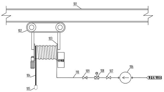
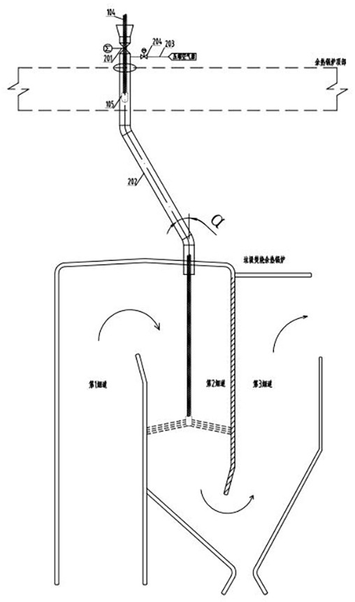
[0033] A waste incineration waste heat boiler online hydraulic ash cleaning system, such as figure 1 and figure 2 As shown, it includes cleaning parts and several prefabricated pipes 202 arranged in an array. The cleaning parts are connected with a first driving part for driving them to move laterally, and the moving path of the cleaning parts passes directly above each prefabricated pipe 202 .

[0034] Such as figure 1 As shown, the first driving part includes an installation guide rail 101 and a traveling mechanism 102 moving along the installation guide rail 101 , and the cleaning part is connected under the traveling mechanism 102 . In this embodiment, the installation guide rail 101 includes a crossbeam and a bottom plate welded to the bottom of the crossbeam. The traveling mechanism 102 includes four traveling wheels abutting on the bottom plate, and two traveling wheels are symmetrically arranged on both sides of the crossbeam. The traveling mechanism 102 can It is a...

Embodiment 2

[0045] The structure of this embodiment is roughly the same as that of Embodiment 1, the difference is that:

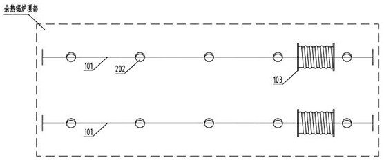
[0046] This embodiment adopts the U-shaped layout method, such as Figure 4 As shown, there are two rows of prefabricated pipes 202 connected to the top of the waste heat boiler, and a U-shaped steel structure track (installation guide rail 101) is installed on the top of the waste heat boiler, and a hydraulic ash cleaning device (cleaning part) is connected to ensure a hydraulic ash cleaning The stroke of the device on the U-shaped steel structure track can cover all the pre-opened round holes and prefabricated pipes 202 on the top of the waste heat waste heat boiler, so as to meet the ash cleaning requirements of the second and third flues in turn.

[0047] Compared with Embodiment 2, Embodiment 1 needs to configure one more hydraulic dust removal device, and the cost will increase. However, two hydraulic dust removal devices can work at the same time, and the work ...


PUM


Abstract

The invention discloses an online hydraulic ash removal system of a waste incineration waste heat boiler, relates to an online ash removal system of a hearth, and solves the problems that dead angles which cannot be cleaned easily exist, and the cleaning efficiency is poor in the prior art. The online hydraulic ash removal system comprises a cleaning part and a plurality of prefabricated pipelines, the cleaning part is connected with a first driving part used for driving the cleaning part to transversely move, and the moving path of the cleaning part passes through the upper portions of the prefabricated pipelines. The lower ends of the prefabricated pipelines communicated into a boiler flue, and stop valves for opening and closing are arranged on the prefabricated pipelines. The cleaning part comprises a cleaning nozzle and a second driving part, and the second driving part drives the cleaning nozzle to move up and down in the prefabricated pipelines. The effects that accumulated ash and coke in a flue are moved efficiently, arrangement is convenient, adjustment is flexible, the work efficiency is high, and the operation and maintenance cost are saved are achieved.

Description

technical field [0001] The invention relates to an online ash cleaning system for a furnace, in particular to an online hydraulic ash cleaning system for waste heat boilers incinerated. Background technique [0002] As one of the important equipment for waste heat utilization, waste incineration waste heat boiler is particularly important to ensure its efficient and stable operation. During the operation of the waste heat boiler, dust accumulation on the heating surface is a common phenomenon, which will reduce the flow area of ​​the flue gas side of the waste heat boiler, increase the heat transfer resistance of the heat receiving surface of the waste heat boiler, and ultimately lead to the production capacity of the waste heat boiler and due to the complex and diverse components of municipal solid waste and high water content, the coke formed on the heat exchange surface during the incineration process has the characteristics of strong cohesiveness and strong corrosion. ...

Claims


Application Information

Patent Timeline
IPC IPC(8): F23J3/02F23G5/46
CPCF23J3/02F23J3/026F23G5/46
Inventor 曹德标林蒙赵平宋小康李军李阳顾春华姜杭杰王允旭
Owner CHINA TIANYING
Learn More