
Laser beam coaxial same-wave-surface control system and method

A control system and laser beam technology, applied in the field of optical engineering, can solve the problem of not considering the performance degradation of beam combining, and achieve the effects of short response time, elimination of coaxial wave plane error, pointing error and focal plane error

Pending Publication Date: 2021-10-26
LASER FUSION RES CENT CHINA ACAD OF ENG PHYSICS
View PDF15 Cites 7 Cited by
  • Summary
  • Abstract
  • Description
  • Claims
  • Application Information

AI Technical Summary

Problems solved by technology

[0003] The existing closed-loop control or automatic alignment device for laser beam combining mainly uses sensors to monitor the beam pointing information of each sub-beam laser in real time, and eliminates the pointing error of each sub-beam laser in real time through feedback control of the tilting mirror to realize multi-beam The coaxial emission, that is, the existing technology mainly controls the coaxiality of each sub-beam laser, considering the change of the focal point in the plane, but does not consider the decrease of the beam combination performance caused by the focal plane change of the focal point, such as CN201210152113.4 based on Laser Beam Common Aperture Power Combining System with Beam Stabilization Closed-loop Control

Method used


Image

  • Laser beam coaxial same-wave-surface control system and method
  • Laser beam coaxial same-wave-surface control system and method
  • Laser beam coaxial same-wave-surface control system and method

Examples


Embodiment 1

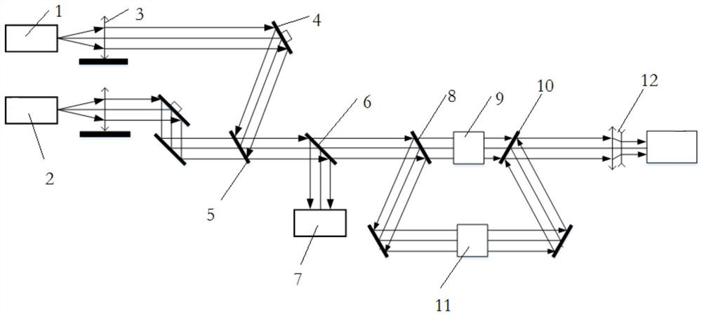
[0071] Such as figure 1 As shown, a laser beam coaxial coaxial control system includes: multiple input sub-beam lasers, sampling mirror 6, beam splitting unit and processor, wherein the wavelengths of multiple input sub-beam lasers are different, and the input sub-beams There are no less than 2 laser beams. The input sub-beam lasers are transmitted to the first beam combining element 5 through the collimation transmission unit to be combined and output to form a beam combining laser. The beam combining lasers are transmitted and reflected by the sampling mirror 6 and then divided into measurement lasers. And the main laser, the main laser can enter the laser emission system 7 to act on the target according to actual needs, the beam separation unit divides the measurement laser into multiple measurement sub-beam lasers, ensuring that the wavefront sensor can separately collect the wavefronts of the multi-channel measurement sub-beam lasers For aberration, the processor calculat...

Embodiment 2

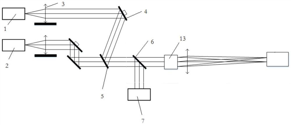
[0093] Such as image 3 As shown, the same parts of this embodiment and Embodiment 1 will not be repeated, and the difference is:

[0094] The beam splitting unit can also be a dispersive element 13, the dispersive element 13 spatially separates the measuring laser light to form multiple measurement sub-beam lasers, and the multi-channel measurement sub-beam lasers become independent image points on the image sensor, realizing the image sensor The spot information of the multi-channel measurement sub-beam laser is collected in different regions. Further, the number of paths of the measuring sub-beam laser is the same as that of the input sub-beam laser. Preferably, the image sensor is a CCD.

[0095] A control method for a laser beam coaxial coaxial co-wave surface control system, comprising the following steps:

[0096] Step S201, move the dispersive element 13 out of the optical path, adjust the first input sub-beam laser 1, so that the light spots are respectively locate...


PUM


Abstract

The invention relates to a laser beam coaxial same-wave-surface control system and method, and belongs to the technical field of optical engineering.The laser beam coaxial same-wave-surface control system comprises multiple paths of input sub-beam lasers, a sampling mirror, a light beam separation unit and a processor, and the input sub-beam lasers are transmitted to a first beam combining element through a collimation transmission unit to form a combined laser; the combined laser is divided into a measuring laser and a main laser through a sampling mirror, the measuring laser is divided into multiple measuring sub-beam lasers through the light beam separation unit, wavefront aberrations of the multiple measuring sub-beam lasers can be collected respectively, the wavefront aberrations are calculated through a processor, pointing information and defocusing information are obtained, and pointing control and focal plane control of the input sub-beam lasers are realized. By means of the light beam separation unit, one wavefront sensor or an image sensor collects wavefront information or light spot information of multiple paths of lasers respectively, pointing information and defocusing information are obtained through calculation of a processor, a driving device is used for adjustment, closed-loop control is achieved, and the pointing error and the focal plane error of the light path are eliminated.

Description

technical field [0001] The invention belongs to the technical field of optical engineering, and in particular relates to a laser beam coaxial and co-wave surface control system and method. Background technique [0002] Due to the limitations of thermal effects, nonlinear effects and other factors of fiber lasers, the laser output of single-fiber single-mode is limited to the order of 10,000 watts. To obtain higher power levels, it is necessary to use multiple beams to combine beams. Beam combining is divided into coherent combining and incoherent combining. Spectral combining, as a way of incoherent combining, has been widely used because of its relatively simple design and high-quality high-power beams. Multiple sub-beam lasers with slightly different wavelengths are collimated and turned into parallel light, and then superimposed in space through a dispersion element, thereby increasing the total output power of the combined beam and having excellent beam quality. However...

Claims


Application Information

Patent Timeline
IPC IPC(8): G02B27/10G02B27/00
CPCG02B27/10G02B27/0012
Inventor 杨英王德恩陈良明张鑫郑胜亨廖予祯郭雨源韩伟田野邓学伟王芳许党朋杨敏杨开栋刘昊李明中袁强袁晓东胡东霞
Owner LASER FUSION RES CENT CHINA ACAD OF ENG PHYSICS
Learn More