
Non-isolated three-phase buck-boost rectification converter and control method

A non-isolated, converter technology, applied in the non-isolated three-phase buck-boost rectifier converter and control field, can solve the problem that the current-conducting capability of the buck switching device cannot be fully utilized, the current-conducting path devices are many, and the unsuitable Cost requirements and other issues, to achieve the effect of reducing restrictions, low loop on-resistance, and reducing the difficulty of control

Pending Publication Date: 2021-10-26
NANJING UNIV OF AERONAUTICS & ASTRONAUTICS +1
View PDF0 Cites 0 Cited by
  • Summary
  • Abstract
  • Description
  • Claims
  • Application Information

AI Technical Summary

Problems solved by technology

[0004] The object of the present invention is to provide a non-isolated three-phase buck-boost rectifier converter and its control method, which can solve the problems in the above-mentioned prior art that the two-stage converter needs multiple conversions, there are too many diversion path devices and the inability to fully utilize the step-down rectifier The current conductivity of the pressure switch device leads to large loss, which is not suitable for the technical problem of application in places with relatively high cost requirements

Method used


Image

  • Non-isolated three-phase buck-boost rectification converter and control method
  • Non-isolated three-phase buck-boost rectification converter and control method
  • Non-isolated three-phase buck-boost rectification converter and control method

Examples


Embodiment 1

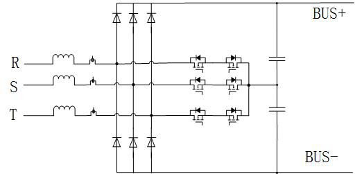
[0053] Such as Figure 4 As shown, a non-isolated three-phase buck-boost rectifier converter includes an input rectifier bridge group, a step-down switch unit and an energy storage freewheeling unit; the input rectifier bridge group includes first to third rectifier bridges FB1~ FB3, the first to third rectifier bridges FB1 to FB3 each include four diodes, and the four diodes are connected in series in pairs in the same direction to form two bridge arm groups with the same function, and the two bridge arm groups are connected in parallel to form Two AC input ports, that is, the midpoint of two diodes connected in series in the bridge arm group, a rectified output positive terminal, that is, the cathode of the bridge arm group, and a rectified output negative terminal, that is, the anode of the bridge arm group; the step-down switch The unit includes the thirteenth to the eighteenth diodes D13~D18 and the first to the sixth switch tubes Q1~Q6, and the energy storage freewheelin...

Embodiment 2

[0093] Such as Figure 16 As shown, Embodiment 2 proposes a modified embodiment based on Embodiment 1, including at least two non-isolated three-phase buck-boost rectifier converters as described in Embodiment 1, each non-isolated The three-phase buck-boost rectifier converters are connected in parallel, and the working phases of the first to sixth switching tubes Q1~Q6 of each non-isolated three-phase buck-boost rectifier converter are interleaved according to 1 / N high-frequency switching cycles , where N is the total number of parallel non-isolated three-phase buck-boost rectifier converters.

[0094] The control method of embodiment 2 is the same as that of embodiment 1. Through the "high" and "middle" mode PWM drive signal control methods described in embodiment 1, N non-isolated three-phase buck-boost rectifiers connected in parallel can be respectively The converter is controlled, and the working phases of the first to sixth switching tubes Q1~Q6 of the N parallel-conne...


PUM


Abstract

The invention relates to a non-isolated three-phase buck-boost rectification converter and a control method. The non-isolated three-phase buck-boost rectification converter comprises an input rectifier bridge group, a buck switch unit and an energy storage follow current unit. The input rectifier bridge group comprises a first rectifier bridge, a second rectifier bridge and a third rectifier bridge, the buck switch unit comprises a first switch tube, a second switch tube, a third switch tube, a fourth switch tube, a fifth switch tube and a sixth switch tube, and the energy storage follow current unit comprises a nineteenth diode and a twentieth diode, a seventh switch tube, a first follow current inductor, a second follow current inductor, a first filter capacitor, a second filter capacitor, a third filter capacitor and a fourth filter capacitor. According to the invention, the input rectifier bridge group and the step-down switch unit in the three-phase rectifier converter are multiplexed to the maximum extent by applying the middle-mode PWM driving signal and the high-mode PWM driving signal to the switch tube, so that the converter is suitable for a wide range of medium and small power output voltage; or the output voltage is in a range from multiple to multiple input phase voltage, and high efficiency and high power density are needed.

Description

technical field [0001] The present application relates to the technical field of power electronics, in particular to a non-isolated three-phase buck-boost rectifier converter and a control method. Background technique [0002] At present, the power of electrical equipment is getting larger and larger, and more and more electrical equipment adopts three-phase power supply mode. If the electrical equipment does not have the power factor correction (PFC) function, it will greatly damage the power quality of the grid. In severe cases It may even lead to the breakdown of the power grid. In order to meet the quality requirements of the power grid, reduce harmonic pollution to the power grid or cause unnecessary transmission burden on the distribution network, three-phase electrical equipment must have PFC function or add filtering devices to meet the requirements of relevant regulations. [0003] Generally speaking, for the rectification conversion circuit with three-phase AC inp...

Claims


Application Information

Patent Timeline
IPC IPC(8): H02M7/219H02M7/217H02M1/44
CPCH02M7/219H02M7/2173H02M1/44
Inventor 李伦全陈乾宏刘斌
Owner NANJING UNIV OF AERONAUTICS & ASTRONAUTICS
Learn More