

A cyclone type high-efficiency sedimentation device
A high-efficiency sedimentation and cyclone device technology, applied in the direction of sedimentation separation, separation of sediments by centrifugal force, separation method, etc., can solve the problems of heavy management and maintenance workload, many sludge discharge valves, easy to block, etc., to achieve easy operation management, Easy to clean and not easy to clog
- Summary
- Abstract
- Description
- Claims
- Application Information
AI Technical Summary
Problems solved by technology
Method used
Image

Examples
Embodiment 1
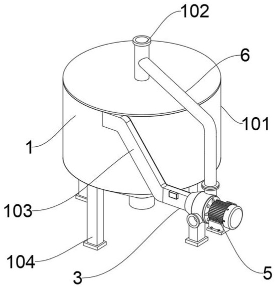
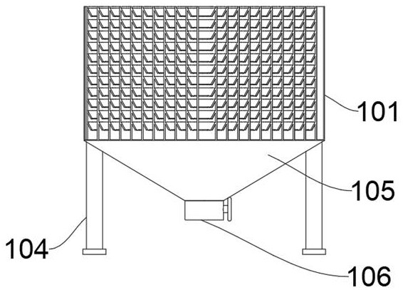
[0034] Please refer to FIG. The top center of the circular cylindrical 101 is inserted with an inlet pipe 102, and the outer top of the circular cylindrical body 101 is inserted with a water pipe 103. The bottom welding of the mudduted 105 has four support foot 104, and the bottom of the mutager 105 is provided. The mud valve 106, the inner portion of the swirling precipitation device 1 is provided with a swirl device 2, and the outlet of the swirl precipitate 1 is provided with a flow measuring device 3, and a control device 4, a flow measuring device 3 is mounted. 3 The end of the terminal is connected to a water pump 5.
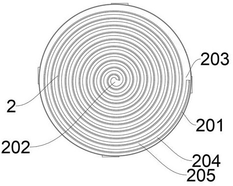
[0035]The swirl device 2 includes a spiral plate 201, the spiral plate 201 is fixed to the inside of the circular cylindrical body 101, and the middle portion of the spiral plate 201 is an inlet portion 202, and the outer portion of the spiral plate 201 is a water port 203, the water port 202 and the water pipe 102 Connecting, the water port 203 is in communic...
Embodiment 2
[0038] Refer to 4, the foundation of the first embodiment is different in that the swirl device 2 includes a spiral plate 201, the spiral plate 201 is fixedly connected to the interior of the circular cylindrical body 101, and the middle of the spiral plate 201 is an inlet 202. The outer portion of the spiral board 201 is an effluent port 203, and the inlet 202 is in communication with the water pipe 102, and the water port 203 is in communication with the water pipe 103, and the inner wall of the spiral plate 201 is welded, and the slurry plate 204 is formed with the vertical surface. At 30 ° angles, a gap is left between between the slant plate 204 and the spiral plate 201 to form a vertical passage 205.
[0039] The top of the slant plate 204 can also be welded with a baffle 206, and the baffle 206 is ≥ 30 ° with the bottom edge angle of the slant plate 204.
[0040] The top of the slant plate 204 can also be welded with a honeycomb tube 207.
[0041] A plurality of baffles 206...
Embodiment 3
[0043] Please refer to 6, which is different from the basis of Examples 1, 2, where the flow measuring device 3 includes a measuring tube 301, and the measuring tube 301 is welded at the end of the water pipe 103, and the inner wall of the measuring tube 301 is welded. Waterproof The cartridge 312, the bottom activity of the waterproof case 312 is connected to the rotating shaft 303, and the rotating shaft 303 is inserted at the top of the movable plate 302, and the bottom portion of the movable plate 302 is in contact with the bottom inner wall of the measuring tube 301, and the right end of the rotary shaft 303 is fixedly connected to the adjustment knob 310, The card slot 306 is opened on the top left side of the movable plate 302, and the inner fitting of the card slot 306 is fitted with the card member 304, the left side of the card member 304 is fixedly connected to the spring 305, and the inner wall of the left side of the measuring tube 301 is also opened. The groove 306, ...
PUM
 Abstract
Description
Claims
Application Information