Ship spraying robot capable of perceiving and recognizing specific marks based on computer vision
A technology of computer vision and sprayer, which is applied in the direction of manipulators, spraying devices, manufacturing tools, etc., can solve the problem of precise spraying in small areas, and achieve good spraying quality, increased intelligence, and strong performance.
- Summary
- Abstract
- Description
- Claims
- Application Information
AI Technical Summary
Problems solved by technology
Method used
Image
Examples
Embodiment 1
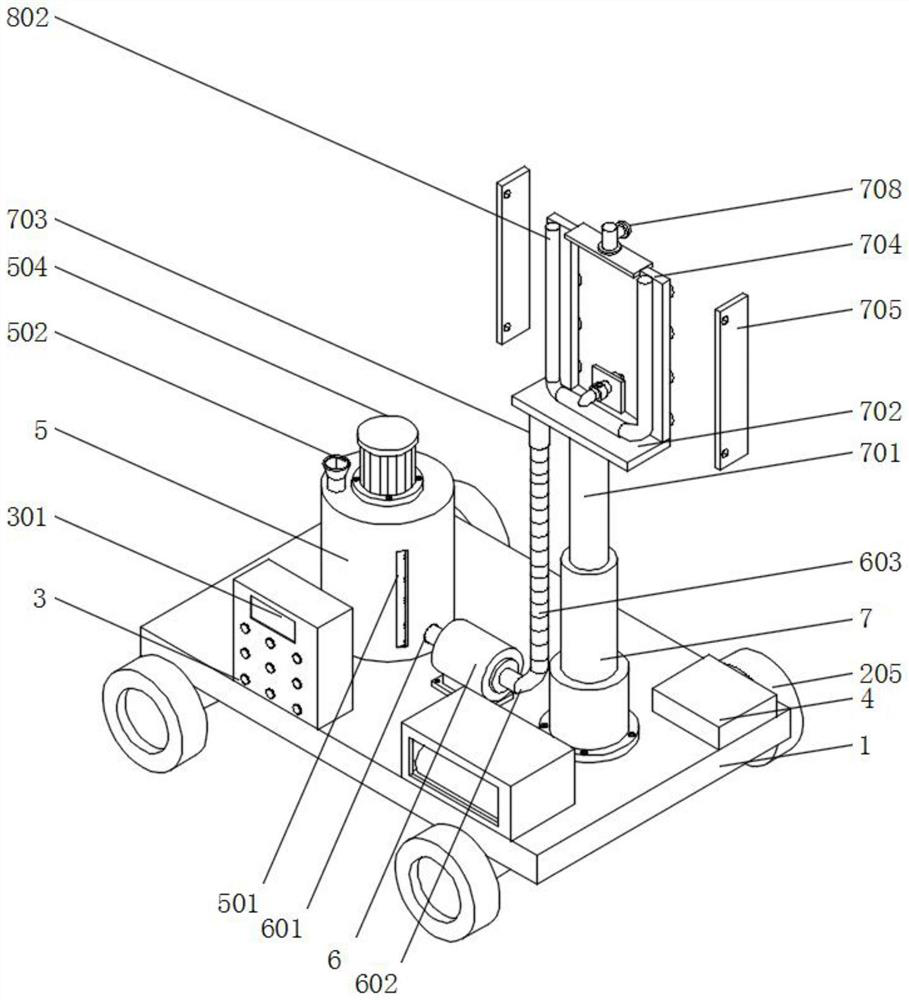
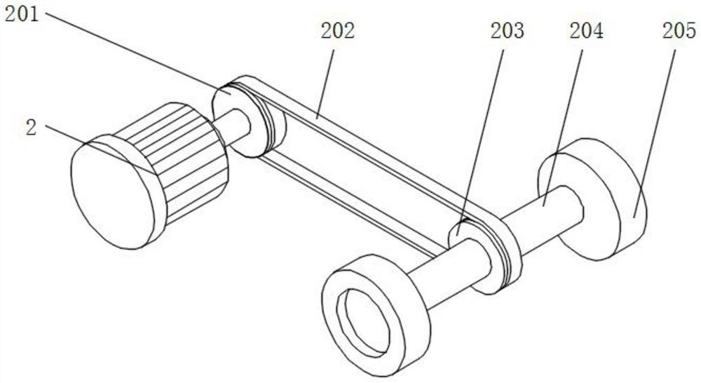
[0043] Embodiment 1 includes a mobile base 1 and a first motor 2, the bottom of the mobile base 1 is equipped with the first motor 2, the top of the mobile base 1 is equipped with a battery box 101, the inside of the battery box 101 is equipped with a storage battery 102, the mobile base 1 It provides an installation position for the top spraying device, and also plays a role of connection. The equipment on the top can be connected through the mobile seat 1, so that the spraying device is integrated, and it is convenient to move. The battery box 101 enables the battery 102 to be installed. Play a protective role to prevent the battery 102 from being damaged. After the battery 102 is powered on, it can convert electrical energy into chemical energy for storage. When it needs to be used, it can convert chemical energy into electrical energy for use. The spraying device provides electricity. The output end of the first motor 2 is equipped with a first runner 201, the outside of th...
Embodiment 2
[0045] Embodiment 2 includes an installation box 4 and a storage tank 5. An installation box 4 is installed on the top of the mobile seat 1, and the installation box 4 is located on one side of the controller 3. The bottom inner wall of the installation box 4 is installed with a first installation plate 401, a GPS positioning module 402 is installed on the top of the first mounting plate 401, a computer vision module 403 is installed on the top of the first mounting plate 401, and the computer vision module 403 is located in front of the GPS positioning module 402, and the top of the first mounting plate 401 The sensory recognition module 404 is installed, and the sensory recognition module 404 is located in front of the computer vision module 403, and the installation box 4 provides an installation position for the internal operation module to prevent the module from being damaged during operation and play a role of protection. The first installation The board 401 provides ins...
Embodiment 3
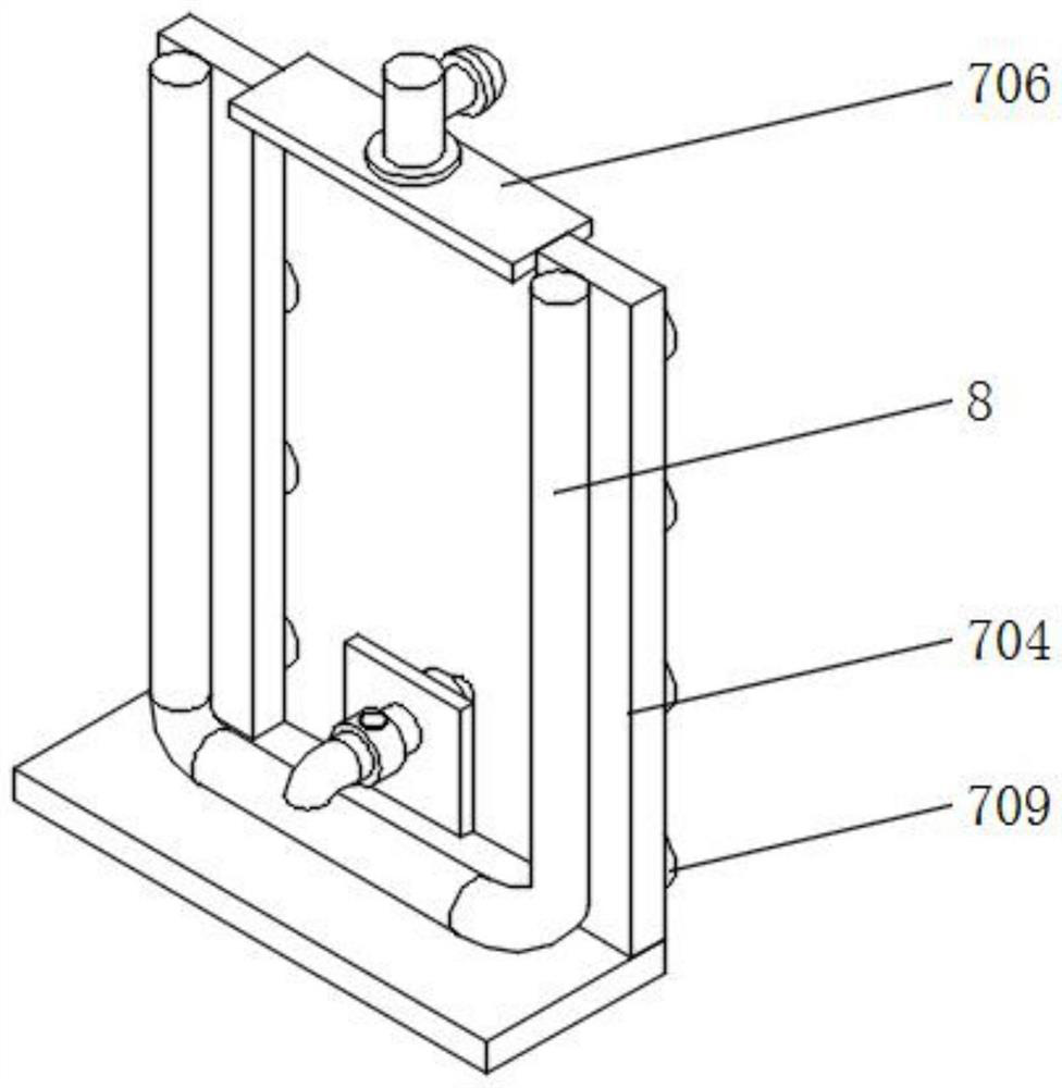
[0047]Embodiment 3 includes a pressure pump 6 and a pneumatic cylinder 7, a pressure pump 6 is installed on the top of the moving base 1, a feed pipe 601 is installed on the input end of the pressure pump 6, and one end of the feed pipe 601 is installed in the storage barrel 5 One side of the pressure pump 6 is equipped with a discharge pipe 602, and one end of the discharge pipe 602 is equipped with a telescopic pipe 603. After the pressure pump 6 is energized, it can convert electrical energy into kinetic energy, so that the paint can be transmitted. The transmission provides power, the feed pipe 601 provides space for the paint in the storage tank 5 to enter the interior of the pressure pump 6, and the discharge pipe 602 provides space for the discharge of the paint, so that the paint can be discharged from the inside of the pressure pump 6, The telescopic tube 603 can be stretched, and the expansion and contraction of the telescopic tube 603 will not affect the movement of ...
PUM
 Abstract
Description
Claims
Application Information
 - R&D
- Intellectual Property
- Life Sciences
- Materials
- Tech Scout
- Unparalleled Data Quality
- Higher Quality Content
- 60% Fewer Hallucinations
Browse by: Latest US Patents, China's latest patents, Technical Efficacy Thesaurus, Application Domain, Technology Topic, Popular Technical Reports.
© 2025 PatSnap. All rights reserved.Legal|Privacy policy|Modern Slavery Act Transparency Statement|Sitemap|About US| Contact US: help@patsnap.com


