Metal plate rolling and cooling integrated equipment

A metal plate, integrated technology, applied in the field of metal plate rolling, can solve the problems of metal plate offset, increase the labor and danger of the staff, avoid deflection, improve safety and automation, and reduce waste. Effect

Active Publication Date: 2021-10-29
江苏超璞智能装备有限公司
View PDF7 Cites 2 Cited by
  • Summary
  • Abstract
  • Description
  • Claims
  • Application Information

AI Technical Summary

Problems solved by technology

[0004] In view of this, the present invention solves the problem that when the metal plate is rolled, due to the high pressure of the equipment and the deformation of the metal plate itself, it is easy to cause the metal plate after each extrusion to be offset before being squeezed again. In some cases, it is often necessary to manually adjust its position, which increases the workload and danger of the staff. A metal plate rolling and cooling integrated equipment is provided.

Method used


Image

  • Metal plate rolling and cooling integrated equipment
  • Metal plate rolling and cooling integrated equipment
  • Metal plate rolling and cooling integrated equipment

Examples


Embodiment 1

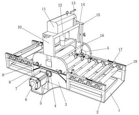
[0034] Such as Figure 1-Figure 7 As shown, a metal plate rolling and cooling integrated equipment includes a bottom plate 1, the upper surface of the bottom plate 1 is fixed with a frame 3 and a support frame 2 by bolts, and the support frame 2 is symmetrically distributed on both sides of the frame 3, and the frame The top of the frame 3 is fixed with a gantry 10 by bolts, and the inner wall of the top of the gantry 10 is fixed with a hydraulic cylinder 12 by bolts. Both sides of the frame 3 are provided with a first chute, and the first chute is slidingly connected with a first chute. Sliding block 21, the first sliding block 21 is rotatably connected with pressing roller 22, is fixed with lifting frame 211 by bolt between the tops of two first sliding blocks 21, and the top of lifting frame 211 and hydraulic cylinder 12 hydraulic rods One end is fixed, and the hydraulic cylinder 12 is activated, which can drive the lifting frame 211 to move, so that the pressure roller 22 ...

Embodiment 2

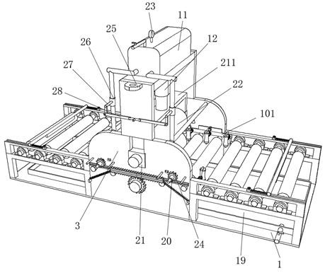
[0038] refer to Figure 1-Figure 7 , the present invention provides a new technical solution, a metal plate rolling and cooling integrated equipment, including a base plate 1, the upper surface of the base plate 1 is fixed with a frame 3 and a support frame 2 by bolts, and the support frame 2 is symmetrically distributed on the machine Both sides of the frame 3, the top of the frame 3 is fixed with a gantry 10 by bolts, the both sides of the gantry 10 are welded with a pull plate 25, and one side of the pull plate 25 is provided with a hanging hole, and the top inner wall of the gantry 10 The hydraulic cylinder 12 is fixed by bolts, the first chute is provided on both sides of the frame 3, the first slider 21 is slidably connected in the first chute, and the pressure roller 22 is rotatably connected between the first slider 21 A lifting frame 211 is fixed between the tops of the two first sliders 21 by bolts, and the top of the lifting frame 211 is fixed to one end of the hydr...


PUM


Abstract

The invention relates to metal plate rolling and cooling integrated equipment, and belongs to the technical field of metal plate rolling. The metal plate rolling and cooling integrated equipment comprises a bottom plate, a rack and supporting frames are fixedly connected to the upper surface of the bottom plate, the supporting frames are symmetrically distributed on the two sides of the rack, a portal frame is fixedly connected to the top of the rack, a hydraulic cylinder is fixedly connected to the inner wall of the top of the portal frame, first sliding grooves are formed in the two sides of the rack, first sliding blocks are movably connected into the first sliding grooves, a pressing roller is movably connected between the first sliding blocks, and a lifting frame is fixedly connected between the tops of the two first sliding blocks. After a metal plate is extruded, the extruded metal plate is limited through a limiting plate, so that the situation that the extruded metal plate deflects on a supporting roller is avoided, and meanwhile, through automatic discharging of a cooling liquid, waste of the cooling liquid is reduced, the metal plate can be automatically pushed, manual operation is avoided, and the automation degree of the equipment is improved.

Description

technical field [0001] The invention belongs to the technical field of metal plate rolling, and relates to integrated equipment for rolling and cooling metal plates. Background technique [0002] As we all know, metal plate refers to the general designation of metal materials or plates with metal characteristics mainly composed of metal elements, including pure metal plates, alloy plates, etc., and some metal plates will use rolling when they are produced. The plate is extruded and deformed, while the rolling method is to place the metal plate between two rolling rollers, and then continuously adjust the distance between the two rolling rolls to squeeze the metal plate to achieve the required thickness . [0003] However, the metal plate rolling equipment used in the market usually needs to reciprocate the rolling of the metal plate during use, and when the metal plate is rolling, due to the high pressure of the equipment, the metal plate itself will also deform , it is ea...

Claims


Application Information

Patent Timeline
Patent Type & Authority Applications(China)
IPC IPC(8): B21B13/02B21B39/34B21B45/02
CPCB21B13/02B21B39/34B21B45/0218B21B2013/021
Inventor 马圣华
Owner 江苏超璞智能装备有限公司
Why Eureka
Try Eureka