
Cooling system of coiling block of coiling machine

A technology of cooling system and coiling machine, applied in metal rolling, manufacturing tools, metal processing equipment, etc., can solve problems such as coil chilling, affecting product quality, and temperature rise, so as to improve use efficiency and product quality , the effect of improving the service life

Pending Publication Date: 2021-10-29
CHANGZHOU BAOLING HEAVY IND MACHINERY
View PDF12 Cites 1 Cited by
  • Summary
  • Abstract
  • Description
  • Claims
  • Application Information

AI Technical Summary

Problems solved by technology

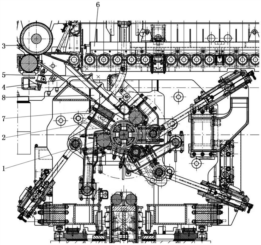
[0005] In a coiling system, the coiling work is alternately performed by two coilers, but the coiling time of one coiler is usually about 90 seconds, and then the coiling aid mechanism 2 and the movable slide plate 5 are opened, and the A larger space is formed on the outer side of the coil for unloading the rolled steel coil. The time required for unloading the steel coil is about 30 seconds. In order to ensure the safety of the next coiling, after the steel coil is unloaded Mechanism 2 and movable slide 5 must return to the position to be rolled. After the roll-assisting mechanism 2 and movable slide 5 return to the position to be rolled, the time for the head of the strip to reach the pinch roller 3 is about 20 seconds, and During the coiling process, the reel 1 is subjected to high-temperature heat transfer on the strip steel, which increases the temperature of the reel 1 itself. From the foregoing, it can be known that the time after the separation of the reel 1 and the steel coil is 20 seconds, the reel 1. The heat dissipation can only be carried out within the time of 20 seconds. The existing coiler does not have a corresponding heat dissipation or cooling structure for the reel 1. Continuous coiling at the above-mentioned high temperature of 800 to 900 ° C will quickly It will cause thermal expansion of the reel 1 and deformation of the reel 1 due to the inability to dissipate heat, and the distance between the reel 1 and the rolling aid mechanism 2 is set, which will cause the strip steel wound on the reel 1 The distance between the coiling aid mechanism 2 and the coiling aid mechanism 2 is narrowed. If the distance is insufficient, the strip steel will collide with the coiling aid mechanism 2 and cause abnormal noise, which not only affects the quality of the product, but also reduces the service life of the fan-shaped plate and the coiling aid roller.
If after the unloading of the steel coil is completed, the coil assisting mechanism 2 is in the open state, and the spray water pipe in the example is used to cool the coil 1, not only will the continuous coiling of the coiler be interrupted, but also the water tube will spray a large amount of water on the coil The drum forms chills, which can cause the drum to crack

Method used


Image

  • Cooling system of coiling block of coiling machine
  • Cooling system of coiling block of coiling machine
  • Cooling system of coiling block of coiling machine

Examples


Embodiment Construction

[0022] Combine below Figure 1 to Figure 6 The present invention will be described.

[0023] Such as figure 1 The coiler shown includes a reel 1, a roll-assisting mechanism 2, a pinch roller 3, a fixed slide 4, and a movable slide 5. The roll-assisting mechanism 2 is arranged around the reel 1. One or four, the rolling aid mechanism 2 in the present embodiment is three, with the drum 1 as the axis, the three rolling aid mechanisms 2 are evenly arranged around the drum 1, the pinch roller 3 and the fixed slide plate 4 One end of the movable slide plate 5 is hinged on the strip conveying device 6 , and the other end of the movable slide plate 5 is a free end and is provided with a guide roller 7 .

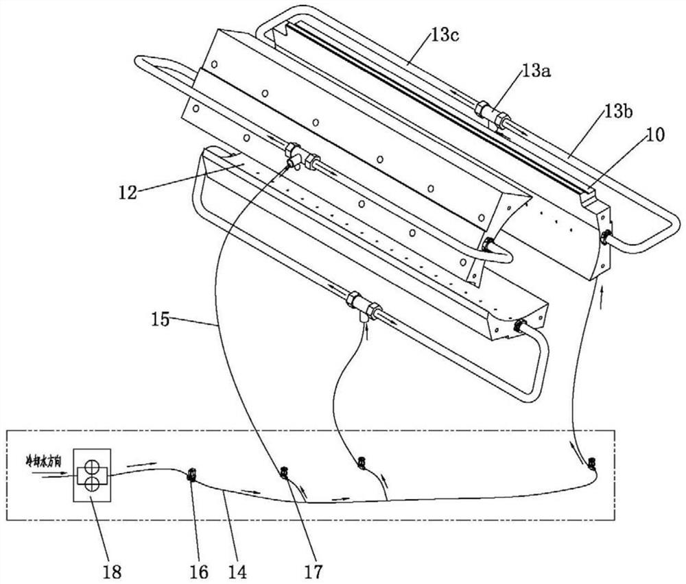
[0024] The present invention improves the coiler of the above-mentioned structure, and the specific improvement is to add a cooling system for the reel 1 to be rolled, such as figure 2 As shown, the cooling system of the reel of the coiler in this embodiment includes a plurality ...


PUM


Abstract

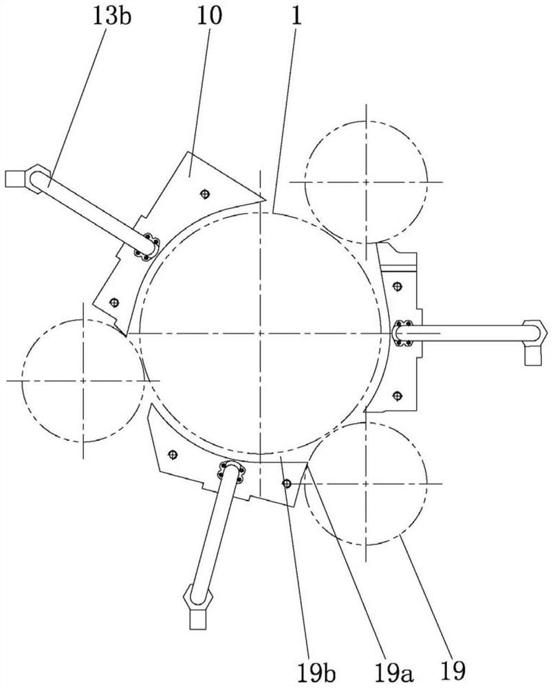
The invention discloses a cooling system of a coiling block of a coiling machine. Each coiling assisting mechanism comprises an arc-shaped plate which is matched with the coiling block to form a coiling area, each arc-shaped plate is provided with a cooling medium input hole and a cooling medium output hole for spraying a cooling medium to the coiling block, and the cooling medium output hole communicates with the cooling medium input hole; the cooling system further comprises a cooling medium injection assembly, and the cooling medium input hole in each arc-shaped plate is connected with the cooling medium injection assembly; and when a steel coil on a coiling block is unloaded, after the coiling assisting mechanisms return to coiling waiting stations, the cooling medium is injected into the cooling medium input hole through the cooling medium injection assembly, then the cooling medium is sprayed to the rotating coiling block through the cooling medium output hole, spraying of the cooling medium to the coiling block is stopped until strip steel is coiled, and the cooling system enables continuous coiling of the coiling machine to be maintained. According to the system, the coiling block can be cooled, and continuous coiling of strip steel can be guaranteed.

Description

technical field [0001] The invention relates to the technical field of strip steel coiling, in particular to a cooling system for a coiler reel. Background technique [0002] The coiler is an auxiliary equipment in the steel rolling workshop that coils hot-rolled or cold-rolled steel into a coil shape. It is arranged after the finished stand on the hot strip continuous rolling mill (hot continuous rolling unit), cold strip continuous rolling mill and wire rod rolling mill. , on a single-stand reversing cold strip mill, it is installed before and after the rolling mill. [0003] The structure of the existing coiler is as follows: comprising a reel 1, a roll-assisting mechanism 2, a pinch roller 3, a fixed slide 4, and a movable slide 5; Usually there are three, evenly arranged around the reel 1, the pinch roller 3 is matched with one end of the fixed slide 4, one end of the movable slide 5 is hinged on the strip conveying device 6, and the other end of the movable slide 5 I...

Claims


Application Information

Patent Timeline
Patent Type & Authority Applications(China)
IPC IPC(8): B21B15/00
CPCB21B15/00B21B2015/0057
Inventor 王军董春光蒋国进吴忠冯湘源
Owner CHANGZHOU BAOLING HEAVY IND MACHINERY
Learn More