Jacket type center frame clamp of numerical control equipment
What is Al technical title?
Al technical title is built by PatSnap Al team. It summarizes the technical point description of the patent document.
A numerical control equipment, jacket-type technology, applied in metal processing equipment, clamping, manufacturing tools, etc., can solve problems such as failure to meet design requirements, thread deformation, high pressure, etc., to achieve low cost, small deformation of parts, and low cost Effect
Pending Publication Date: 2021-10-29
杭州泽正机械有限公司
View PDF6 Cites 0 Cited by
Summary
Abstract
Description
Claims
Application Information
AI Technical Summary
This helps you quickly interpret patents by identifying the three key elements:
Problems solved by technology
Method used
Benefits of technology
Problems solved by technology
The current processing method is to clamp one end with an ordinary chuck, and the other end uses an ordinary center frame to clamp the outer circle, so as to process the thread. However, due to excessive pressure, the thread after processing will be deformed, which cannot meet the design requirements, resulting in scrap.
Method used
Image
Click on the blue label to locate the original text in one second.
Reading with bidirectional positioning of images and text.
Examples
Embodiment Construction
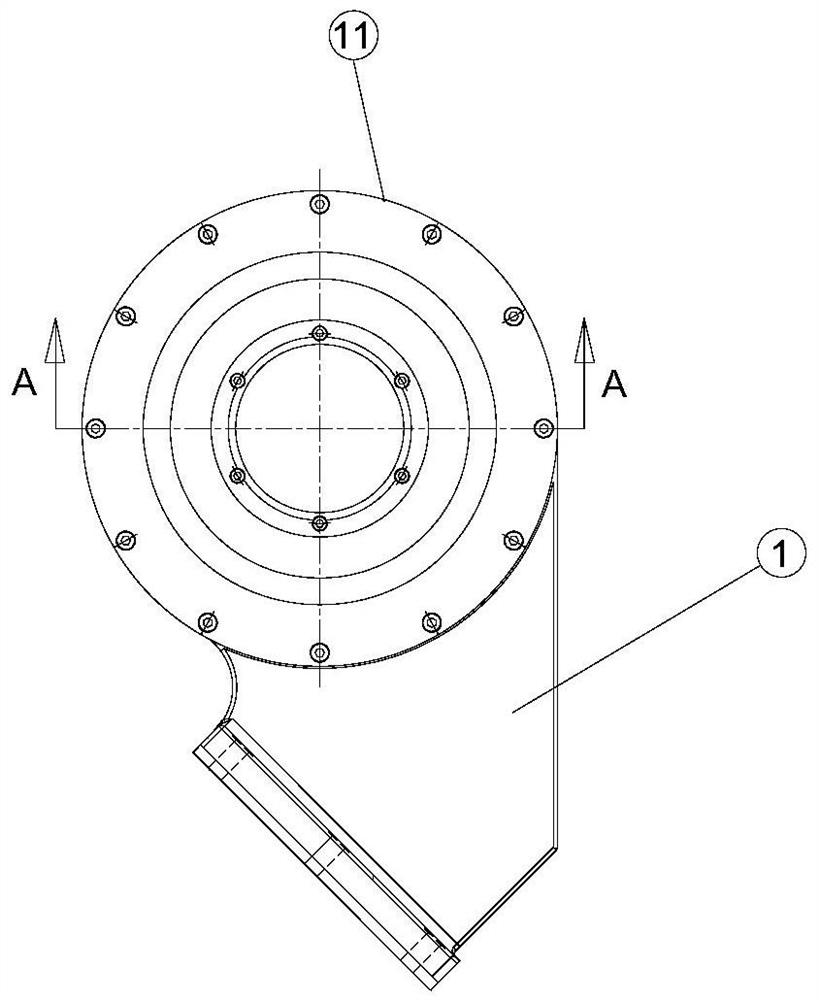
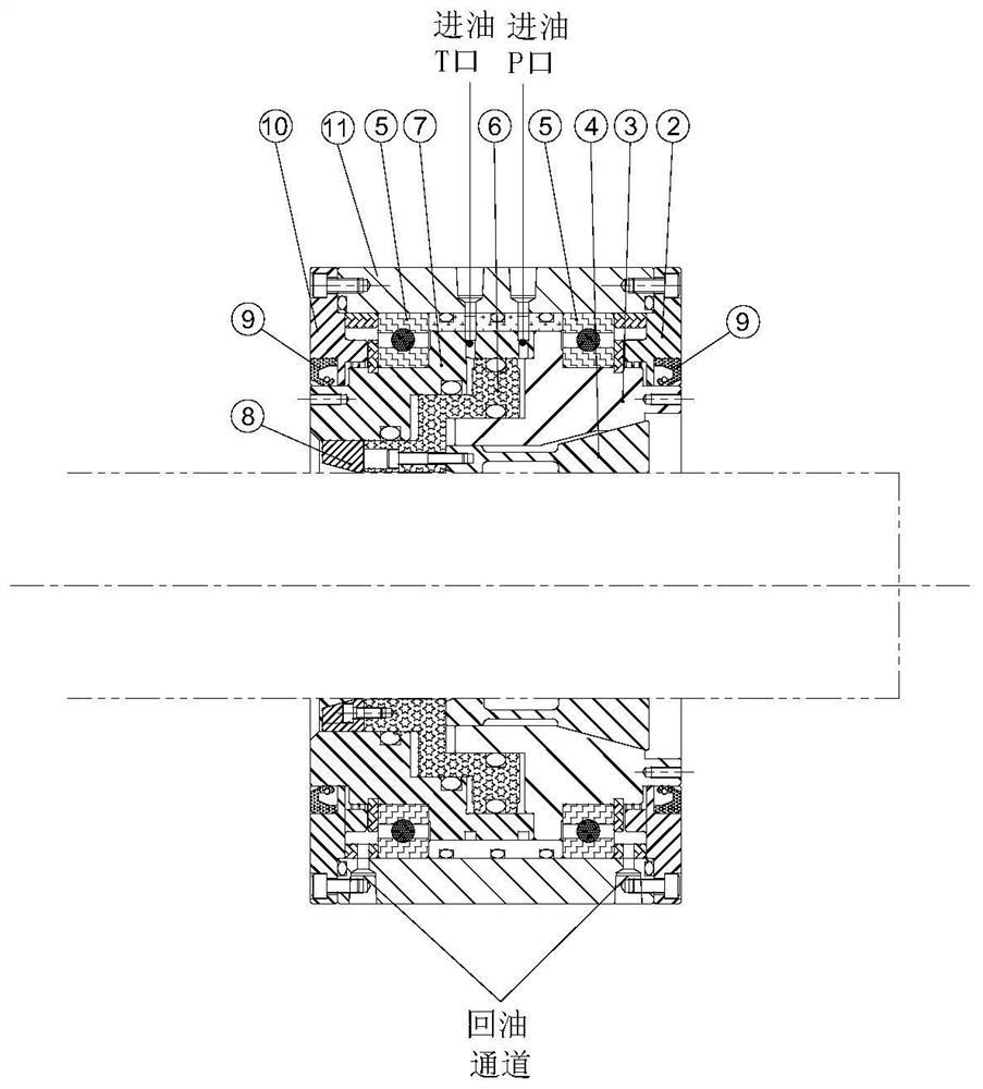
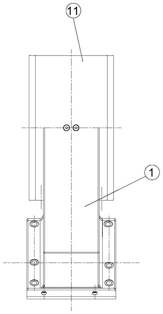
[0019] refer to Figure 1 to Figure 3 , a jacket type center frame clamp for numerical control equipment in the present invention, comprising a clamp base 1, an end cover 2, a jacket seat 3, a jacket 4, a bearing 5, a piston 6, an oil cylinder body 7, and a rear cover 10, the clamp There is an installation base 11 on the base 1, and the jacket seat 3 and the oil cylinder body 7 are respectively installed on both ends of the installation base 11 through bearings 5, and the jacket seat 3 is used for precise positioning when the jacket is clamped The outer side of the jacket seat 3 facing away from the cylinder body 7 is provided with an end cover 2, the outer side of the oil cylinder body 7 facing away from the jacket seat 3 is provided with a rear cover 10, and the oil cylinder body 7 faces the jacket seat One end of 3 has an oil chamber, and the oil cylinder body 7 is also provided with an oil inlet P port, an oil inlet T port and an oil return passage connected with the oil c...
PUM
Abstract
The invention provides a jacket type center frame clamp of numerical control equipment. The jacket type center frame clamp comprises a clamp base, an end cover, a jacket seat, a jacket, bearings, a piston, an oil cylinder body and a rear cover, a mounting base is arranged on the clamp base, the jacket seat and the oil cylinder body are mounted at the two ends of the mounting base through the bearings respectively, the end cover is arranged at one end, back to the oil cylinder body, of the outer side of the jacket seat, the rear cover is arranged at the end, back to the jacket seat, of the outer side of the oil cylinder body, an oil cavity is formed in the end, facing the jacket seat, of the oil cylinder body, the oil cylinder body is further provided with an oil inlet channel opening P, an oil inlet channel opening T and an oil return channel which communicate with the oil cavity, the piston is arranged in the oil cavity, the jacket is installed at the end, facing the end cover, of the piston, and the jacket is arranged in an inner cavity of the jacket seat. Compared with an existing center frame, the clamp can be installed on an existing numerical control machine tool, universality is high, surrounding type clamping is achieved, part deformation is extremely small, the machining precision is improved, and the qualified rate of products is increased.
Description
【Technical field】 [0001] The invention relates to the technical field of fixtures, in particular to a jacket-type center frame fixture for numerical control equipment. 【Background technique】 [0002] Thin-walled pipe parts generally appear in the military and aerospace fields. The processing of thin-walled parts has always been a difficult problem. Among them, the external turning thread processing is the most difficult. The ordinary clamping method can easily cause deformation of the parts during processing, which in turn affects Manufacturing precision of parts. With the continuous development of the manufacturing industry in the military and aerospace fields, the requirements for the manufacturing precision of thin-walled tube parts are also getting higher and higher. The current processing method is to clamp one end with an ordinary chuck and the other end to clamp the outer circle with an ordinary center frame to process the thread. However, due to excessive pressure, ...
Claims
Application Information
Patent Timeline
Application Date:The date an application was filed.
Publication Date:The date a patent or application was officially published.
First Publication Date:The earliest publication date of a patent with the same application number.
Issue Date:Publication date of the patent grant document.
PCT Entry Date:The Entry date of PCT National Phase.
Estimated Expiry Date:The statutory expiry date of a patent right according to the Patent Law, and it is the longest term of protection that the patent right can achieve without the termination of the patent right due to other reasons(Term extension factor has been taken into account ).
Invalid Date:Actual expiry date is based on effective date or publication date of legal transaction data of invalid patent.