Bionic arm

A bionic arm and palm technology, applied in the field of bionic arms, can solve problems such as narrow application range, and achieve the effect of fast response and large deformation

Pending Publication Date: 2021-10-29
TSINGHUA UNIV +1
View PDF15 Cites 0 Cited by
  • Summary
  • Abstract
  • Description
  • Claims
  • Application Information

AI Technical Summary

Problems solved by technology

However, the electrothermally actuated composite material can only bend in one direction, and its application range is narrow

Method used


Image

  • Bionic arm
  • Bionic arm
  • Bionic arm

Examples


Embodiment Construction

[0043] The nanofiber actuator provided by the present invention, the actuation system using the actuator and other applications will be described in detail below with reference to the accompanying drawings.

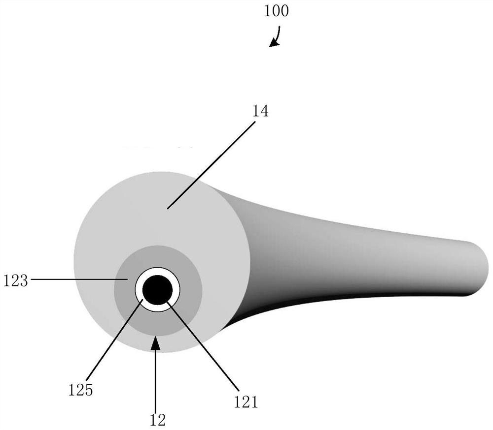
[0044] See figure 1 , the first embodiment of the present invention provides a nanofiber actuator 100 , which includes a composite structure 12 and a vanadium dioxide layer 14 . The composite structure 12 includes a carbon nanotube wire 121 and an aluminum oxide layer 123, the aluminum oxide layer 123 is coated on the surface of the carbon nanotube wire 121 and arranged coaxially with the carbon nanotube wire 121, the The vanadium dioxide layer 14 is coated on the surface of the composite structure 12 , and the vanadium dioxide layer 14 and the composite structure 12 are arranged non-coaxially.

[0045] The composite structure 12 includes the carbon nanotube wire 121 and the aluminum oxide layer 123 . The composite structure 12 may only consist of the carbon nanotube wi...


PUM

PropertyMeasurementUnit
diameteraaaaaaaaaa
thicknessaaaaaaaaaa
thicknessaaaaaaaaaa

Abstract

The invention relates to a bionic arm which comprises a bionic palm and at least one finger. Each finger is a nanofiber actuator which comprises a composite structure body and a vanadium dioxide layer, wherein the composite structure body comprises a carbon nanotube line and an aluminum oxide layer, the aluminum oxide layer coats the surface of the carbon nanotube line and is coaxially arranged with the carbon nanotube line, the vanadium dioxide layer coats the surface of the composite structure body, and the vanadium dioxide layer and the composite structure body are not coaxially arranged.

Description

technical field [0001] The invention relates to a bionic arm, in particular to a bionic arm based on carbon nanotubes. Background technique [0002] The working principle of the actuator is to convert other energy into mechanical energy. There are three ways to achieve this conversion: through electrostatic field into electrostatic force, that is, electrostatic drive; through electromagnetic field into magnetic force, that is, magnetic drive; using materials Thermal expansion or other thermal properties effect the conversion of energy, ie thermal actuation. [0003] Actuators that convert energy using the above-mentioned thermal drive are thermal actuators. Existing thermal actuators are usually polymer-based film-like structures, which can be actuated by raising the temperature of the polymer through an electric current and causing significant volume expansion. The principle of thermally actuated devices dictates that electrode materials must possess good electrical condu...

Claims


Application Information

Patent Timeline
Patent Type & Authority Applications(China)
IPC IPC(8): B25J9/10
CPCB25J9/1095A61F2/586A61F2002/701A61F2/70A61L27/08A61L27/306A61L27/50A61L2400/12F03G7/06114B82Y30/00H02N10/00A61L27/047A61L27/10A61L27/165A61L27/042
Inventor 王广马赫金翔原华魏洋李群庆姜开利范守善
Owner TSINGHUA UNIV
Why Eureka
Try Eureka