Supercharge Your Innovation With Domain-Expert AI Agents!

Preheater device for blast furnace hot blast stove

A hot blast stove and preheater technology, applied in blast furnaces, blast furnace details, blast furnace parts, etc., can solve problems such as poor preheating effect and inconvenient cleaning of dust, saving trouble and improving service life.

Inactive Publication Date: 2021-10-29
上海雷林工业设备有限公司
View PDF6 Cites 0 Cited by
  • Summary
  • Abstract
  • Description
  • Claims
  • Application Information

AI Technical Summary

Problems solved by technology

[0006] Aiming at the deficiencies of the prior art, the present invention provides a blast furnace hot blast stove preheater device, which solves the inconvenience of the existing hot blast stove preheater to filter the dust and slag in the exhaust gas of the hot blast stove, and the filtered dust is inconvenient Cleaning, and the problem of poor warm-up

Method used


Image

  • Preheater device for blast furnace hot blast stove
  • Preheater device for blast furnace hot blast stove
  • Preheater device for blast furnace hot blast stove

Examples


Embodiment 1

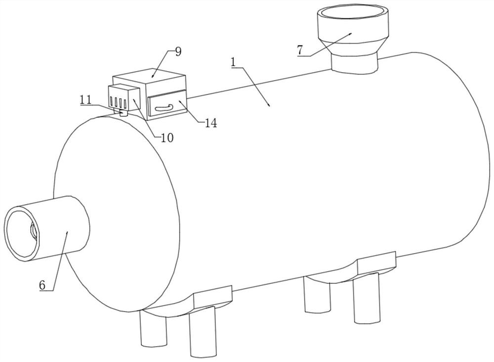
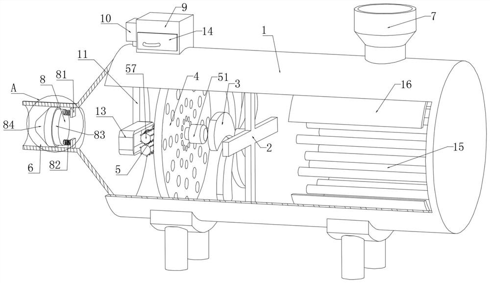
[0029] Embodiment 1: A preheater device for a blast furnace hot blast stove, comprising a preheating barrel 1, a cross support 2 is fixedly connected to the inner cavity wall of the preheating barrel 1, and an exhaust fan 3 is arranged on the left side wall of the cross support 2 to preheat The inner cavity wall of the barrel 1 is fixedly connected with a filter plate 4, the left side wall of the filter plate 4 is provided with a cleaning mechanism 5, the left end surface of the preheating barrel 1 is connected with an air inlet pipe 6, and the upper end surface of the preheating barrel 1 is provided with an outlet pipe. The air duct 7, the inner chamber wall of the air inlet duct 6 is provided with a sealing mechanism 8, the upper end surface of the preheating barrel 1 is provided with a dust collection mechanism 10, and the right side wall of the dust collection mechanism 10 is fixedly connected with a collection box 9, and the dust suction mechanism The lower end surface of ...

Embodiment 2

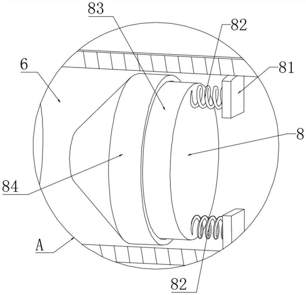
[0030]Embodiment 2: The difference between this embodiment and Embodiment 1 is that the sealing mechanism 8 includes a mounting block 81, a spring 82, a tapered column 83 and a tapered sleeve 84, and the inner cavity wall of the air inlet pipe 6 is symmetrically fixedly connected with a mounting block 81 , a spring 82 is fixedly connected to the left side wall of the mounting block 81 . The left end of the spring 82 is fixedly connected with a tapered column 83, the inner cavity wall of the air inlet pipe 6 is fixedly connected with a tapered sleeve 84, the inner wall of the tapered sleeve 84 is engaged with the tapered column 83, and the preheating barrel 1 is close to the right side The inner cavity wall of the preheating bucket 1 is provided with a thermal insulation ring layer 16, and the right cavity wall of the preheating barrel 1 is evenly and fixedly connected with a heat pipe 15. Through the cooperation of the insulation ring layer 16, the heat pipe 15, the sealing me...


PUM


Abstract

The invention discloses a preheater device for a blast furnace hot blast stove. The preheater device comprises a preheating barrel, wherein the inner cavity wall of the preheating barrel is fixedly connected with a cross-shaped support, the left side wall of the cross-shaped support is provided with a draft fan, the inner cavity wall of the preheating barrel is fixedly connected with a filter plate, the left side wall of the filter plate is provided with a sweeping mechanism, the left end surface of the preheating barrel communicates with an air inlet pipe, a dust suction mechanism is arranged on the upper end surface of the preheating barrel, the right side wall of the dust suction mechanism is fixedly connected with a collecting box, the lower end surface of the dust suction mechanism communicates with a dust suction pipe, the front end surface of the collecting box is slidably connected with a collecting drawer, and a dust outlet pipe of the dust suction mechanism communicates with the collecting box. The invention relates to the technical field of preheaters for hot blast stoves. The preheater device for the blast furnace hot blast stove solves the problem that it is inconvenient for an existing preheater for a hot blast stove to filter dust and slag in tail gas of the hot blast stove, filtered dust is inconvenient to clean, and the preheating effect is poor.

Description

technical field [0001] The invention relates to the technical field of hot blast stove preheaters, in particular to a blast furnace hot blast stove preheater device. Background technique [0002] The hot blast stove is one of the main supporting equipment for the blast furnace in the ironworks. Its function is to heat the blast to the required temperature to improve the benefit and efficiency of the blast furnace. The hot blast stove preheater is a heating surface that uses the flue gas in the boiler tail flue to preheat the air before entering the boiler to a certain temperature through the internal cooling fins. It is used to improve the heat exchange performance of the boiler and reduce energy consumption. [0003] The publication number is: CN201920717229.5 discloses an air preheater for a blast furnace. The blast furnace air preheater includes a flue gas device and an air device. The right side of the flue gas device is provided with an air device. The flue gas device...

Claims


Application Information

Patent Timeline
IPC IPC(8): C21B9/14B01D46/10B01D46/00
CPCC21B9/14B01D46/10
Inventor 吴进福
Owner 上海雷林工业设备有限公司
Features
  • R&D
  • Intellectual Property
  • Life Sciences
  • Materials
  • Tech Scout
  • Unparalleled Data Quality
  • Higher Quality Content
  • 60% Fewer Hallucinations
Learn More