Manufacturing technology of decorative indoor rammed earth column
A production process and decorative technology, applied in the field of architectural decoration, can solve the problems of high cost and large weight of rammed earth columns, and achieve the effects of reducing overall weight, reducing construction difficulty, and reducing manufacturing costs.
- Summary
- Abstract
- Description
- Claims
- Application Information
AI Technical Summary
Problems solved by technology
Method used
Image
Examples
Embodiment 1
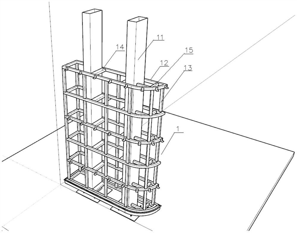
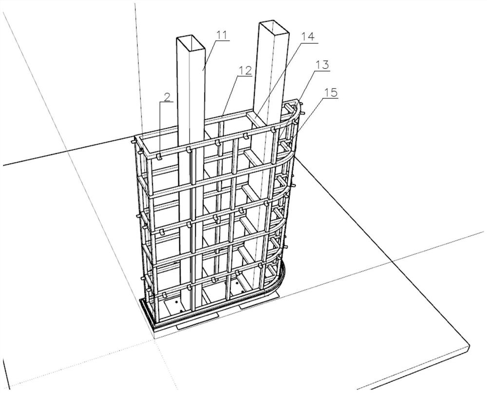
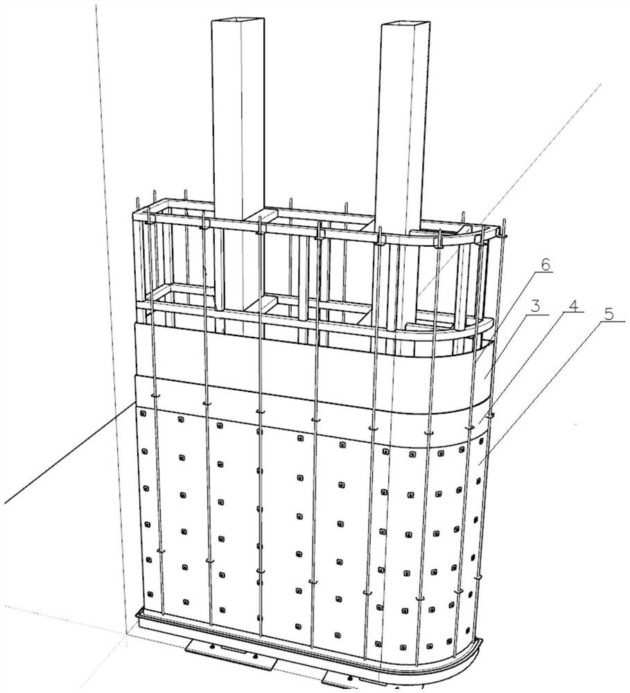
[0042] This embodiment provides a pouring device for indoor decorative rammed earth columns, including a decorative main frame 1 , a base panel, a steel wire mesh 5 , vertical ribs 6 and a pouring mold 9 .
[0043] Such as Figure 1-Figure 2As shown, the decorative main frame 1 is used to form the main structure of the interior decorative rammed earth column. The decorative main frame 1 is connected to the ground to install a pre-embedded plate, which is fixed to the ground by chemical bolts. The size of the pre-embedded plate here is 350 *350*10 mm, the chemical bolts are RM12 chemical bolts, and at the same time, the connection between the decorative main frame 11 and the wall is provided with a pre-embedded board, and the pre-embedded board is fixed to the wall by chemical bolts, the size of the pre-embedded board The size is 200*200*8 mm, and the chemical bolts are RM12 chemical bolts. The embedded boards on the ground and the embedded boards on the wall must be secure aft...
Embodiment 2
[0048] This embodiment provides a manufacturing process of a decorative indoor rammed earth column, including the following steps:
[0049] Step 1. Install the decorative main frame 1, install the pre-embedded plate at the joint between the decorative main frame 1 and the ground, fix the pre-embedded plate to the ground through chemical bolts, and weld the bottom of the decorative main frame 1 to the pre-embedded plate;
[0050] Step 2. Weld the corner code 2 on the corresponding point of the decorative main frame 1;
[0051] Step 3: Set the base panel on the periphery of the decorative main frame 1, first open a hole on the base panel at the position corresponding to the corner code 2, and fix the base panel on the decorative main frame 1 with drilling screws;
[0052] Step 4: Lay steel wire mesh 5 on the outside of the base panel, the end of the corner code 2 passes through the steel wire mesh 5, set the vertical reinforcing rib 6 on the outside of the steel wire mesh 5, and...
PUM
 Abstract
Description
Claims
Application Information
 - R&D
- Intellectual Property
- Life Sciences
- Materials
- Tech Scout
- Unparalleled Data Quality
- Higher Quality Content
- 60% Fewer Hallucinations
Browse by: Latest US Patents, China's latest patents, Technical Efficacy Thesaurus, Application Domain, Technology Topic, Popular Technical Reports.
© 2025 PatSnap. All rights reserved.Legal|Privacy policy|Modern Slavery Act Transparency Statement|Sitemap|About US| Contact US: help@patsnap.com


