Flue gas flow velocity adjusting structure of SCR denitration device

A technology of flue gas flow rate and structure adjustment, which is applied to exhaust gas devices, gas treatment, separation methods, etc., can solve the problem of insignificant adjustment effect of flue gas flow rate, wear and leakage of low-temperature economizer tube bundles, and difficulty in flue gas velocity at the outlet, etc. To achieve the effect of optimizing flue gas flow resistance, reducing flow rate loss, and maintaining uniformity

Pending Publication Date: 2021-10-29
XIAN THERMAL POWER RES INST CO LTD
View PDF0 Cites 0 Cited by
  • Summary
  • Abstract
  • Description
  • Claims
  • Application Information

AI Technical Summary

Problems solved by technology

[0003] The way to adjust the flue gas flow rate at the outlet of the SCR denitrification device in the prior art is to set two sets of deflectors at the corners of the SCR denitrification flue and above the low-temperature economizer, and to connect the outlet of the SCR denitrification device with the bell mouth. Low-temperature economizer, and set a set of equalizers in the flue above the low-temperature economizer to adjust the flue flow rate of the front and rear walls evenly, but according to the measured and adjusted results, the upper part of the low-temperature economizer At the cross section, that is, the root mean square deviation of the flue gas flow velocity on the left and right sides of the front wall of the SCR denitrification outlet is about 38.8%, and the root mean square deviation of the flue gas flow velocity on the left and right sides of the rear wall is about 33.9%, and the average flow velocity deviation of the front and rear walls is about 1.21m / s, the deviation is relatively large. Therefore, the flue gas flow rate adjustment structure at the outlet of the SCR denitrification device in the prior art has no significant effect on the adjustment of the flue gas flow rate. The large difference makes it difficult to uniformly distribute the flue gas velocity at the outlet, causing local wear and leakage of the low-temperature economizer tube bundle, which affects the normal operation of the boiler

Method used


Image

  • Flue gas flow velocity adjusting structure of SCR denitration device
  • Flue gas flow velocity adjusting structure of SCR denitration device
  • Flue gas flow velocity adjusting structure of SCR denitration device

Examples


Embodiment 1

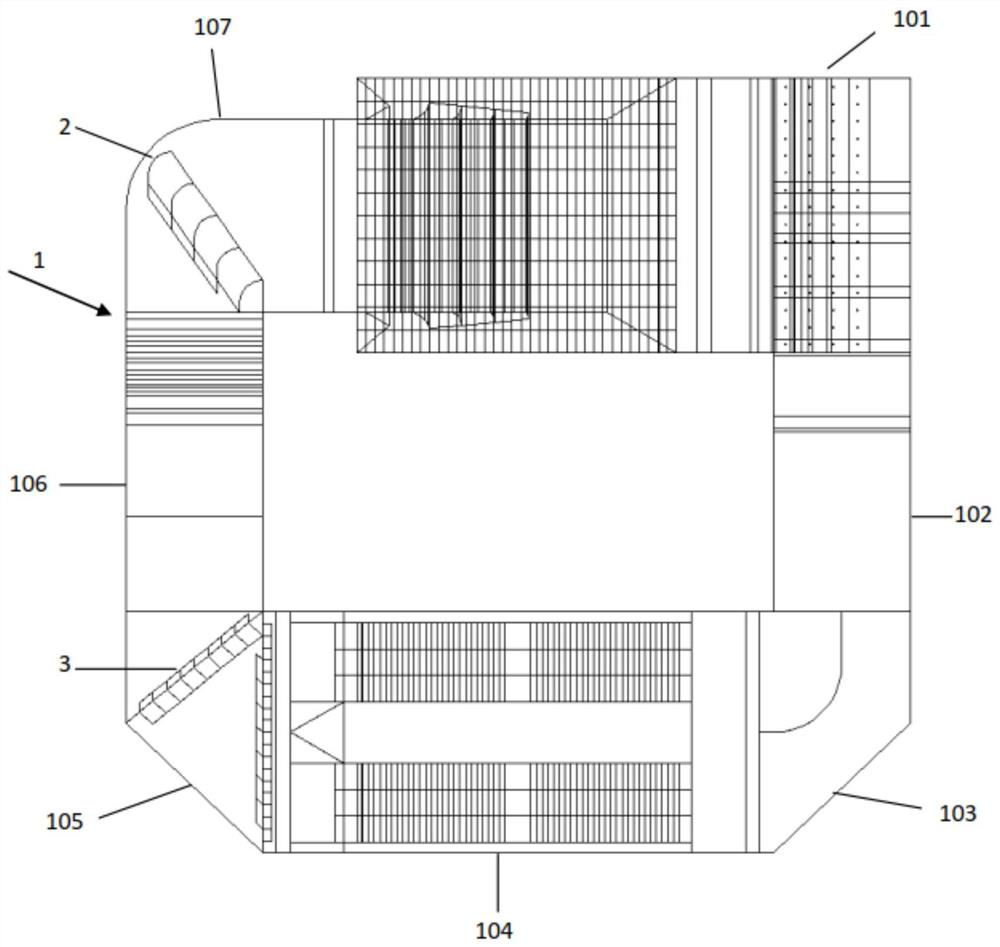
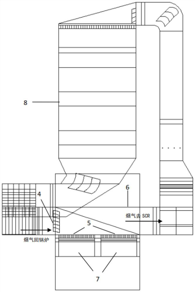
[0054] In this embodiment, a flue gas velocity adjustment structure of an SCR denitrification device is designed, and the specific design is as follows:

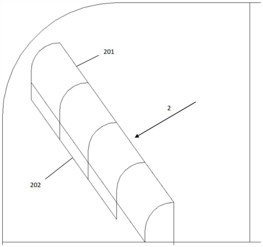
[0055] 1) At the fourth corner flue 107 of the SCR denitrification flue 1, five first deflectors are evenly arranged along the width direction. The arc-shaped diversion part 201 is a 90° arc, and the arc-shaped diversion part 201 is arranged parallel to the outer contour of the fourth corner flue 107, and the rectangular diversion part 202 is parallel to the side of the third straight pipe flue 106, and the arc The radius of the shaped drainage part 201 is 500mm, and the length of the rectangular drainage part 202 is 500mm;

[0056] 2) Arrange the second group of deflectors 3 at the third corner flue 105 of the SCR denitrification flue 1, including the first flue deflector 301, the second flue deflector 302, and the second flue deflector 303 and diagonal guide plate 304; the first flue guide plate 301 is arranged at interva...


PUM


Abstract

The invention provides a flue gas flow velocity adjusting structure of an SCR denitration device, and aims to reduce the flue gas flow velocity deviation of a denitration outlet and uniformize the flue gas flow velocity of the outlet. The structure comprises a first group of flow guide plates, a second group of flow guide plates, a third group of flow guide plates and a group of flow equalizing plates; an SCR denitration flue comprises a first corner flue, a first straight pipe flue, a second corner flue, a third corner flue, a third straight pipe flue and a fourth corner flue; the first group of flow guide plates are arranged in the fourth corner flue; the second group of flow guide plates are arranged in the second corner flue; the third group of flow guide plates comprises a drainage part and a flow guide part which are uniformly arranged at intervals in the height direction of the fourth corner flue, the drainage part is parallel to the upper and lower surfaces of the fourth corner flue, and the flow guide part is parallel to the diagonal surface of a connecting flue; the group of flow equalizing plates comprises a plurality of flow equalizing plates which are arranged at intervals in the length direction of the gas inlet end of a low-temperature economizer, and the flow equalizing plates are vertically connected with the gas outlet end of the flue and are parallel to the cross section of the fourth corner flue.

Description

technical field [0001] The invention relates to the technical field of flue gas flow field simulation in a boiler tail flue, in particular to a flue gas flow adjustment structure of an SCR denitrification device. Background technique [0002] The SCR process is currently the most widely used flue gas denitrification process in China. For coal-fired boilers that are not equipped with SCR devices when they are put into operation, SCR devices can be added at appropriate locations through transformation. Before the SCR denitrification transformation, the flue gas at the tail of the boiler directly enters the low-temperature economizer through the high-temperature preheater from top to bottom. Some small-capacity boilers have a short flue flow and a compact location. The interface of the SCR device is located between the high-temperature preheater and the low-temperature economizer, and the space is relatively limited. When adding an SCR denitrification device, the high-temperatu...

Claims


Application Information

Patent Timeline
IPC IPC(8): F23J15/06F23J15/02F23J11/00F23J13/00B01D53/86B01D53/56
CPCF23J15/06F23J15/02F23J11/00F23J13/00B01D53/8631B01D53/56B01D2258/0283
Inventor 徐晓涛杨世极舒凯李淑宏尚桐袁壮
Owner XIAN THERMAL POWER RES INST CO LTD
Why Eureka
Try Eureka