
High-speed dual-channel synchronous optical signal sampling circuit

A sampling circuit and signal sampling technology, which is applied to electrical components, analog-to-digital converters, code conversion, etc., can solve the problems of not synchronizing signal data, and cannot ideally realize synchronous signal sampling of two optical signals and synchronous data processing, etc. Achieve excellent indicators, stable and reliable test data, and reduce production costs and scrap rates

Pending Publication Date: 2021-10-29
上海天美科学仪器有限公司
View PDF0 Cites 2 Cited by
  • Summary
  • Abstract
  • Description
  • Claims
  • Application Information

AI Technical Summary

Problems solved by technology

[0003] The purpose of the present invention is to provide a high-speed dual-channel synchronous optical signal sampling circuit, which solves the signal transmission time required for sending instructions, and the sampling data of the sample optical signal is no longer synchronous signal data after waiting for the reference optical signal to be sampled. The problem of not ideally realizing the synchronous signal sampling and synchronous data processing of two optical signals

Method used


Image

  • High-speed dual-channel synchronous optical signal sampling circuit
  • High-speed dual-channel synchronous optical signal sampling circuit
  • High-speed dual-channel synchronous optical signal sampling circuit

Examples


Embodiment Construction

[0030] The following will clearly and completely describe the technical solutions in the embodiments of the present invention with reference to the accompanying drawings in the embodiments of the present invention. Obviously, the described embodiments are only some, not all, embodiments of the present invention. Based on the embodiments of the present invention, all other embodiments obtained by persons of ordinary skill in the art without making creative efforts belong to the protection scope of the present invention.

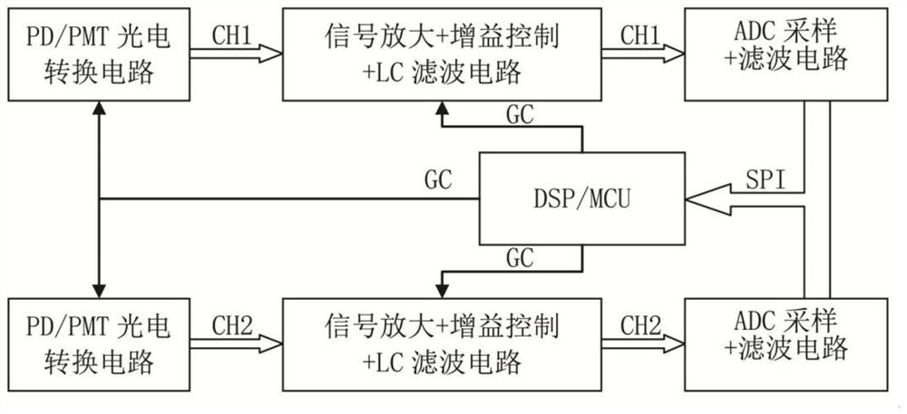
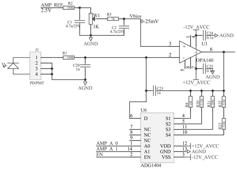
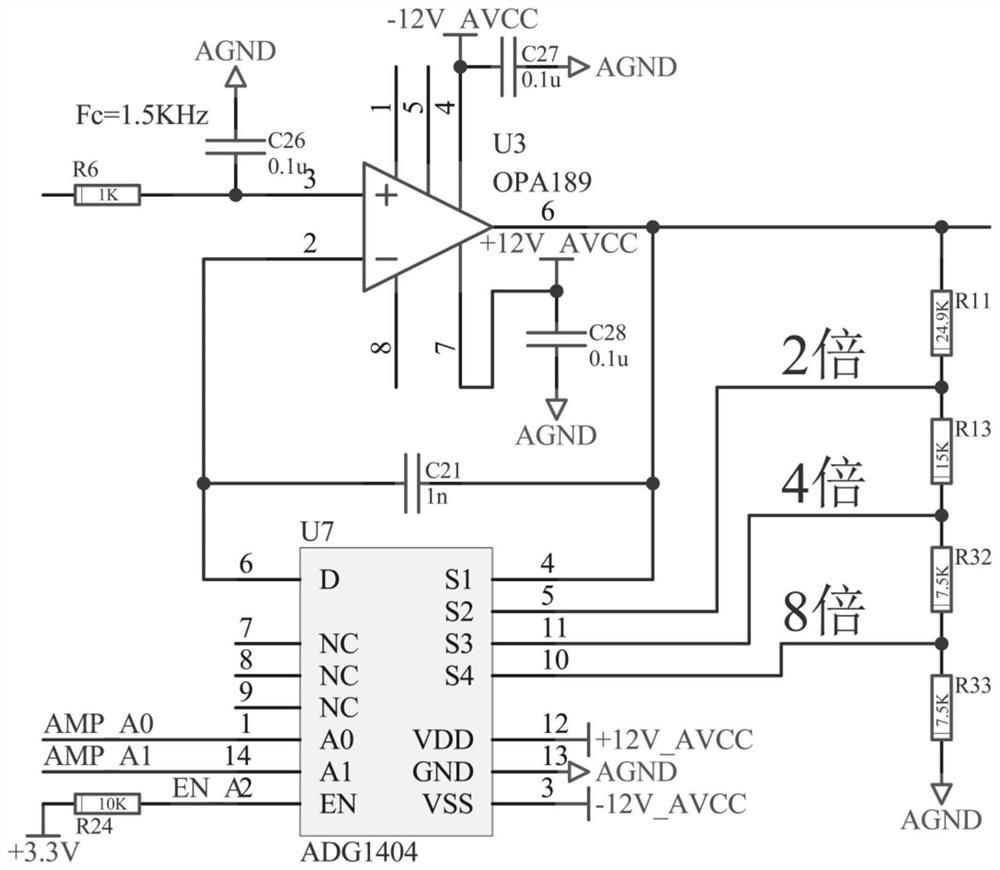
[0031] see Figure 1-8 , the present invention provides a technical solution: a high-speed dual-channel synchronous optical signal sampling circuit, including: a control unit, which includes a photoelectric conversion circuit, a gain control amplifier circuit and an ADC sampling circuit, and the photoelectric conversion circuit 1. The gain control amplifier circuit and the ADC sampling circuit are provided with two groups, the photoelectric conversion circuits...


PUM


Abstract

The invention discloses a high-speed dual-channel synchronous optical signal sampling circuit, which comprises a control unit, and is characterized in that the control unit comprises two groups of photoelectric conversion circuits, two groups of gain control amplification circuits and two groups of ADC sampling circuits. According to the invention, the latest 24-bit ADC sampling chip integrated with three filtering functions at present is adopted; the operational amplifier is high in broadband, ultralow in noise and zero in drift; the two ADC sampling chips use the same system clock and keep synchronous working frequency; the same REF reference voltage is used; the sampling circuit has a two-stage gain control function and a low-pass filtering function; a serial daisy chain mode of an ADC chip and a PIN port control mode are adopted, high-speed synchronous sampling and synchronous data output of two channels are achieved, instructions of a controller do not need to be received, and synchronous data are sent after automatic synchronous sampling.

Description

technical field [0001] The invention relates to the technical field of intelligent instruments and meters, and more specifically relates to a high-speed dual-channel synchronous optical signal sampling circuit. Background technique [0002] At present, there are basically two ADC sampling circuit methods for the sample optical signal and reference optical signal of the dual optical path photometer on the market: 1. Use two ADC chips for CS chip selection and then perform data processing after sampling separately; 2. Use one The multi-channel ADC performs data processing after CH channel selection sampling. Their common feature is that the main controller needs to send control instructions to them. The problem is that sending instructions requires signal transmission time. The sampling data of the sample optical signal is not synchronous signal data after waiting for the reference optical signal to be sampled. The synchronous signal sampling and synchronous data processing o...

Claims


Application Information

Patent Timeline
Patent Type & Authority Applications(China)
IPC IPC(8): H03M1/12
CPCH03M1/1245
Inventor 黄雄随东丽胡志东
Owner 上海天美科学仪器有限公司
Learn More