Biomass liquid fuel production device

A technology of liquid fuel and production equipment, which is applied in the direction of mixers, dissolvers, and mixers with rotating stirring devices, which can solve problems such as reducing performance, hindering liquid flow rate, and affecting filtration efficiency, achieving high filtering effect and ensuring flow rate , Improve the effect of performance

Inactive Publication Date: 2021-11-02
王永强
View PDF0 Cites 1 Cited by
  • Summary
  • Abstract
  • Description
  • Claims
  • Application Information

AI Technical Summary

Problems solved by technology

[0005] Aiming at the deficiencies of the prior art, the present invention provides a biomass liquid fuel production device, which solves the problem of filtering the existing fuel before mixing it, especially for some viscous feed liquid, which will form a liquid on the filter screen. The membrane hinders the flow rate of the liquid, and a large amount of residue will adhere to the surface of the filter, which is prone to clogging, affects the filtration efficiency, and reduces the performance

Method used


Image

  • Biomass liquid fuel production device
  • Biomass liquid fuel production device
  • Biomass liquid fuel production device

Examples


Embodiment example 1

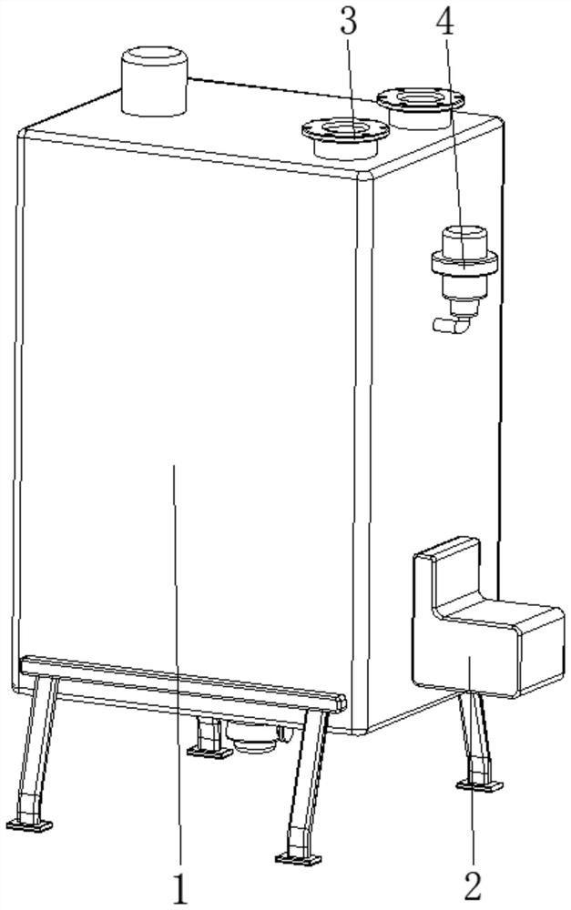
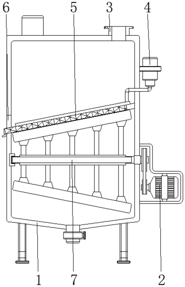
[0030] see Figure 1-6 , the present invention provides a technical solution: a biomass liquid fuel production device, including a housing 1, a power mechanism 2, a feed port 3, and an air pump 4, the power mechanism 2 is arranged on the bottom side of the surface of the housing 1, and The feed port 3 is fixed and connected to the top side of the shell 1, and the air pump 4 is set on the top side of the shell 1;

[0031] The interior of the housing 1 is provided with a filter device 5, a slag discharge port 6, and a mixing device 7. The filter device 5 is arranged inside the shell 1 and is close to the central position. The filter device 5 is connected with the air pump 4, and the slag discharge port 6 is set on one side of the surface of the housing 1 and is located at the position of the filter device 5. The mixing device 7 is arranged inside the housing 1 and is located at the bottom of the filter device 5. The mixing device 7 is connected with the power mechanism 2, which ...

Embodiment example 2

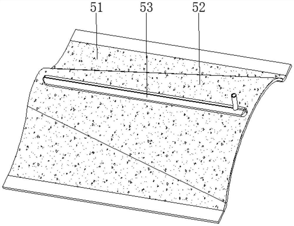
[0033] The filter device 5 is provided with a filter screen main body 51, an arc-shaped conical protrusion 52, and a cleaning device 53. The surface edge of the filter screen main body 51 is fixedly connected with the inner wall of the housing 1, and the arc-surface conical protrusion 52 is arranged on the filter screen main body. 51, the removal device 53 is arranged at the center of the surface of the arc-shaped conical protrusion 52, when the raw material passes through the filter screen main body 51, the residue can be filtered out, and the air pump 4 is used to deliver high-pressure gas, so that the removal device 53 work, and the arc-shaped conical protrusion 52 can cooperate with the mixing device 7 to make full use of its own rotation, so that when mixing materials, it can further perform self-cleaning, and the situation of blockage is not easy to occur.

[0034]Clearing device 53 is provided with base body 531, main air channel 532, spherical inner cavity 533, impact b...

Embodiment example 3

[0036] The mixing device 7 is provided with a rotating roller 71, a stirring rod 72, and a scraping device 73. The end of the rotating roller 71 is connected in rotation with the inner wall of the housing 1, and one end of the rotating roller 71 penetrates the inner wall of the housing 1 and extends to it. Externally, one end of the rotating roller 71 extending to the outside of the housing 1 is connected with the power mechanism 2, one end of the stirring rod 72 is fixedly connected to the surface of the rotating roller 71, and the scraping device 73 is arranged on the side of the stirring rod 72 away from the rotating roller 71. At one end, when the power mechanism 2 drives the rotating roller 71, the stirring rod 72 and the scraping device 73 will rotate accordingly, and then use the staggered arrangement to improve the stirring efficiency of the material liquid, so that the material can be mixed quickly and evenly At the same time, when the scraping device 73 is rotating, i...


PUM


Abstract

The invention discloses a biomass liquid fuel production device which comprises a shell, a power mechanism, a feeding port and an air pump, the power mechanism is arranged on one side of the bottom of the surface of the shell, the feeding port is fixed to and communicates with one side of the top of the shell, the air pump is arranged on one side of the top of the surface of the shell, and a filtering device is arranged in the shell and close to the center position. The filtering device is connected with the air pump in a matched mode, a slag discharging opening is formed in one side of the surface of the shell and located at the position of the filtering device, a mixing device is arranged in the shell and located at the bottom of the filtering device, and the mixing device is connected with the power mechanism in a matched mode. The invention relates to the technical field of fuel production equipment. According to the biomass liquid fuel production device, the anti-sticking effect is achieved, the biomass liquid fuel production device is not prone to being influenced by viscous feed liquid, residues can be automatically cleaned, the blocking situation is not prone to occurring, the filtering effect is high, a viscous liquid film is not prone to being formed, the flow speed of liquid is guaranteed, and the use performance is improved.

Description

technical field [0001] The invention relates to the technical field of fuel production equipment, in particular to a biomass liquid fuel production device. Background technique [0002] With the continuous improvement of people's living standards, the consumption of fuel oil and gas continues to rise. With the shortage of global energy resources, fuel prices continue to soar, which directly affects industrial and agricultural production and people's daily life. Biomass (such as straw, firewood, wood chips, bamboo chips and other agricultural waste) is a renewable resource that can be converted into biomass liquid fuel. Every year, hundreds of millions of tons of agricultural waste in my country are burned by farmers, which is not only a waste resources and pollute the air. Now that fossil energy is becoming more and more exhausted, renewable energy is a new energy source that countries all over the world pay more and more attention to. Moreover, biomass liquid fuel has the ...

Claims


Application Information

Patent Timeline
Patent Type & Authority Applications(China)
IPC IPC(8): B01F7/04B01F15/00B01F15/02B01F3/20B01F23/70
Inventor 王永强
Owner 王永强
Why Eureka
Try Eureka