Supercharge Your Innovation With Domain-Expert AI Agents!

Automatic flaking device for conductive adhesive

A conductive adhesive and automatic technology, applied in metal processing and other directions, can solve problems such as low work efficiency, errors in parallelism or perpendicularity, and affect the conductivity of conductive films, so as to achieve guaranteed quality, high work efficiency, and improved uniformity Effect

Pending Publication Date: 2021-11-02
GUILIN UNIV OF AEROSPACE TECH
View PDF0 Cites 0 Cited by
  • Summary
  • Abstract
  • Description
  • Claims
  • Application Information

AI Technical Summary

Problems solved by technology

[0002] The conductive rubber block is made of conductive silica gel and insulating silica gel alternately layered and superimposed and vulcanized. There is an error in the parallelism or perpendicularity of the stripes inside the rubber block and the cross-section, resulting in uneven distribution of the insulating layer and the conductive layer after the rubber block is sliced. Uniformity, which seriously affects the conductivity of the conductive film
In order to solve this technical problem, in the prior art, the slicing of the conductive adhesive is usually divided into two steps. First, the external shape of the conductive adhesive block is corrected and sliced ​​manually, and the surface of the conductive adhesive block is planed by visual inspection. Ensure that each surface of the processed conductive rubber block is in an orthogonal or parallel relationship with the texture, and then place the corrected conductive adhesive on the slicing device, and continuously slice the conductive rubber block layer by layer according to the specified thickness to complete the slicing process , the manual correction method has low work efficiency, the accuracy cannot be guaranteed, and is greatly affected by the proficiency of workers, which affects the stability of product quality

Method used


Image

  • Automatic flaking device for conductive adhesive
  • Automatic flaking device for conductive adhesive
  • Automatic flaking device for conductive adhesive

Examples


Embodiment Construction

[0022] The following examples of the present invention will be described in detail.

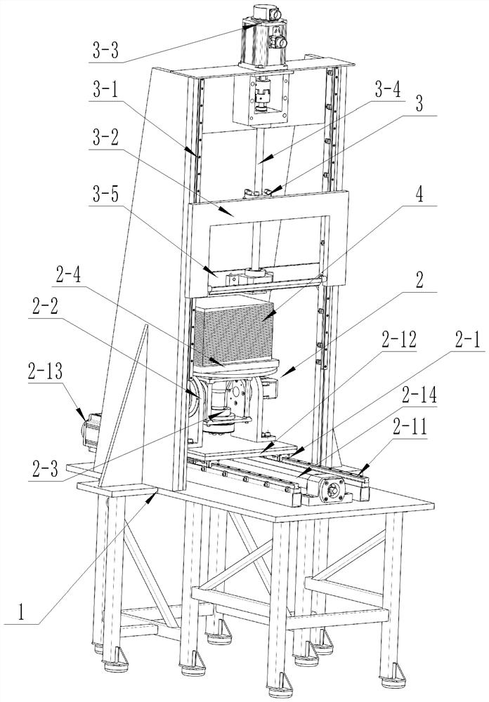
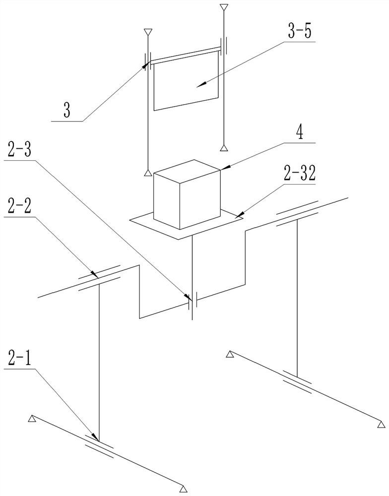
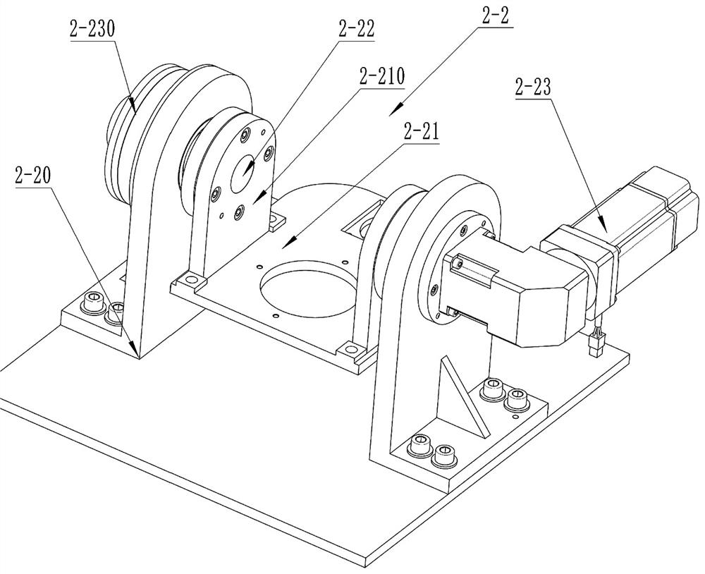
[0023] See Figure 1 to 5 An automatic planing conductive adhesive sheet means, comprising a frame 1, carrying conductive paste platform assembly mounted on the chassis 1, 2, 3 plow assembly and a control module,

[0024] 2 platform assembly includes a feed mechanism 2-1, 2-2 tilt mechanism, rotation mechanism and the conductive adhesive fixing means 2-3, 2-1 feed mechanism comprises a horizontal guide rail and a horizontal frame 1 provided on the slide table 2- 12, a first horizontal guide rails 2-11, 2-12 horizontal slide table connected to the first drive mechanism, the first drive mechanism includes a first servomotor and a first ball screw 2-13 2-14, a first servo 2-13 motor mounted on the frame 1, a first ball screw 2-14 and 2-11 the first guide rail disposed in parallel, the output terminal end of the first ball screw 2-14 and 2-13 of the first servo motor when connected, the level of the b...


PUM


Abstract

The invention belongs to the field of conductive adhesive manufacturing equipment, and particularly relates to an automatic flaking device for conductive adhesive. The device comprises a rack, a platform assembly mounted on the rack and used for bearing the conductive adhesive, a planer tool assembly and a control module, a pitching mechanism comprises a supporting seat, a pitching plate and a pitching shaft, and the pitching plate is driven to rotate along with the pitching shaft; a rotating mechanism comprises a rotating shaft and a platform plate connected with the rotating shaft, and the platform plate is driven to rotate along with the rotating shaft; a conductive adhesive fixing mechanism comprises a vacuum chuck, the vacuum chuck is installed on the platform plate and used for adsorbing a conductive adhesive block to be planed during working, the planer tool assembly comprises a vertical guide rail, a planer tool base and a planer tool blade, a cutting edge of the planer tool blade faces downwards, and the planer tool blade is driven to move along with the planer tool base; and the control module comprises a central processing unit, and an image recognition unit and an execution unit which are electrically connected with the central processing unit. The flaking device can replace manual correction and slicing of the conductive adhesive block, the working efficiency is high, and the reliable quality of finished products is effectively guaranteed.

Description

Technical field [0001] The present invention belongs to the field of equipment for manufacturing the conductive paste, in particular to a conductive paste automatic flaking apparatus. Background technique [0002] Block is made of conductive paste is superimposed after curing of alternating insulating and conductive silicone silicone layered, parallel stripes or the perpendicularity of the cross section of the interior blocks are errors in the gum, resulting in the rubber block slice, the insulating layer and the conductive layer distribution is not uniform, seriously affecting the electrical properties of conductive film. In order to solve this technical problem, the prior art planer sheet of conductive paste is usually performed in two steps, first using the external shape of the conductive paste manually corrected block slicing, visually, the surface of the conductive rubber block flaking, to ensure that the relationship between the conductive paste blocks the processing of th...

Claims


Application Information

Patent Timeline
Patent Type & Authority Applications(China)
IPC IPC(8): B26D1/08B26D5/00B26D7/01
CPCB26D1/08B26D5/005B26D7/018
Inventor 张凌云吕勇张勇张政泼张心仪刘忠李天明徐晓华熊威朱治法谭振瑞赵贵荣
Owner GUILIN UNIV OF AEROSPACE TECH
Features
  • R&D
  • Intellectual Property
  • Life Sciences
  • Materials
  • Tech Scout
  • Unparalleled Data Quality
  • Higher Quality Content
  • 60% Fewer Hallucinations
Learn More