Simple and rapid screen changing method for rotary screen thickener

A thickener and rotary screen technology, applied in pulp dewatering and other directions, can solve the problems of low utilization rate of equipment, many operators, damage to sealing water ring, etc., to achieve less fluctuation of slurry concentration, ensure concentration effect, and high utilization rate of equipment Effect

Pending Publication Date: 2021-11-02
GUILIN QIFENG PAPER
View PDF5 Cites 0 Cited by
  • Summary
  • Abstract
  • Description
  • Claims
  • Application Information

AI Technical Summary

Problems solved by technology

[0007] The purpose of the present invention is to provide a simple and fast screen changing method for a rotary screen thickener, to at least solve the problem that the screen changing method of the rotary screen thickener in the prior art is relatively complicated, and the time required to replace a new surface net It is longer and the technical problems of more operators can be solved, and at the same time, it can solve the problem that the two ends of the drive shaft of the rotary screen cage are easily sealed during the disassembly and reinstallation of the rotary screen cage in the existing method of changing the screen of the rotary screen thickener. The water ring is damaged, and the technical problem that the concentration effect of the rotary screen thickener is affected. Furthermore, it can solve the existing technology of the rotary screen thickener. The close contact of the bottom net of the cylinder screen causes the endless ring surface net to be easily damaged, the equipment utilization rate is low, the slurry concentration fluctuates more, and the refining quality is affected by technical problems

Method used


Image

  • Simple and rapid screen changing method for rotary screen thickener

Examples


Embodiment Construction

[0026] The present invention will be described in further detail below in conjunction with the accompanying drawings and specific embodiments.

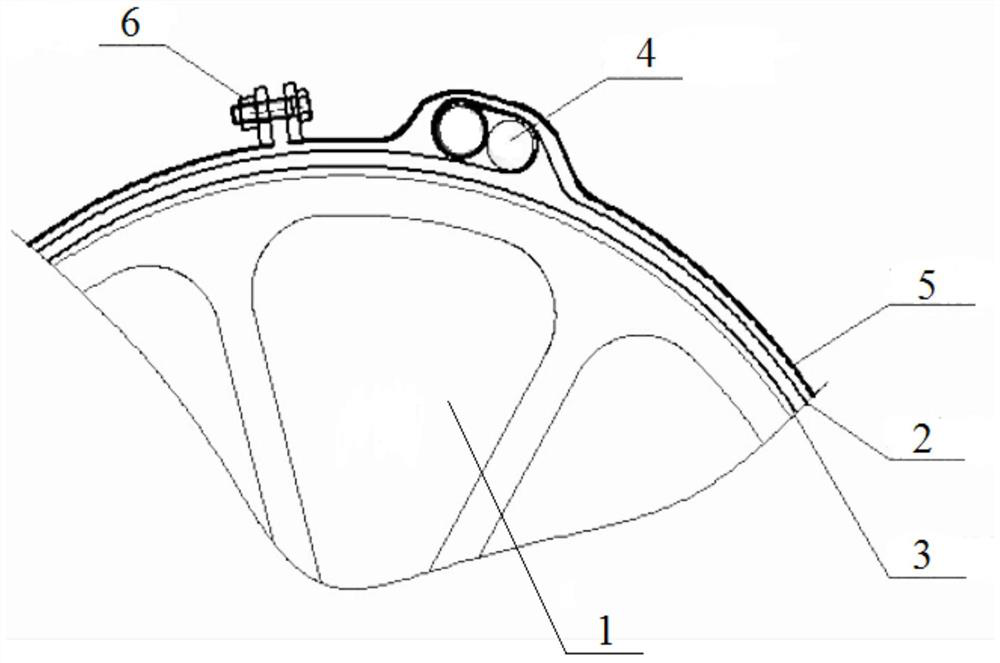
[0027] Such as figure 1 As shown, a simple and fast screen changing method for a rotary screen concentrator according to a preferred embodiment of the present invention involves a new type of surface screen 2 with an end, a stainless steel clamp 4, a tightening hoop 5, a rotary screen cage 1 and a bottom screen 3 of the rotary screen cage , the method is used to replace the damaged surface net of the cylinder 1 surface layer with a new surface net, comprising the following steps:

[0028] S1, open the rotary screen thickener, first remove the damaged surface net of the rotary screen cage 1 surface layer;

[0029] S2, then connect one end of the end-type new surface net 2 around the cylinder cage 1 to the other end, so that the end-type new surface net 2 surrounds the circumference of the cylinder cage 1;

[0030] S3, then use stainl...


PUM


Abstract

The invention discloses a simple and rapid screen changing method for a rotary screen thickener; the method relates to a novel surface screen with an end, stainless steel clamps, a tightening hoop, a rotary screen cage and a rotary screen cage bottom screen; the method is used for changing a damaged surface screen of a surface layer of the rotary screen cage into a new surface screen and comprises the following steps: S1, the rotary screen thickener is started, and firstly, a damaged surface screen of the surface layer of the rotary screen cage is removed; S2, one end of the novel surface screen with the end bypasses the rotary screen cage and is connected with the other end of the novel surface screen with the end, and the novel surface screen with the end surrounds the circumference of the rotary screen cage; S3, the two ends of the novel surface screen with the end are clamped by using stainless steel clamps, and continuously wound until the whole screen surface is uniformly tensioned; and S4, finally, the novel face screen with the end and the stainless steel clamps are locked through the tightening hoop, and screen replacement is completed at the moment. The method can be used for directly replacing a new surface screen in the rotary screen thickener frame, has the characteristics of time saving, labor saving and labor saving, is not easy to damage after the new surface screen is replaced, and is high in equipment utilization rate, small in slurry concentration fluctuation and more stable in grinding quality.

Description

technical field [0001] The invention belongs to the technical field of changing screens of rotary screen thickeners, and relates to a simple and quick screen changing method for rotary screen thickeners. Background technique [0002] In the pulp and paper industry, the rotary screen thickener is mainly used for the dehydration and concentration of pulp. The first principle is to rely on the liquid level difference between the inside and outside of the rotary screen cage, and the second is to use the extrusion force between the pressure roller and the rotary screen cage. Dehydrated. During the dehydration process of the pulp used in papermaking, the surface filter of the cylinder of the cylinder thickener is easily damaged. At this time, a new surface must be replaced in time, otherwise the concentration of the paper material will be unstable, which will seriously affect the quality of refining and the stability of production. Sexuality and even cause slurry loss and so on. ...

Claims


Application Information

Patent Timeline
Patent Type & Authority Applications(China)
IPC IPC(8): D21C9/18
CPCD21C9/18
Inventor 朱和锋
Owner GUILIN QIFENG PAPER
Why Eureka
Try Eureka