
Debris collecting device for vertical shaft excavation hole by drilling and blasting method

A technology of collecting device and drilling and blasting method, which is applied in vertical shaft equipment, sinking, earthwork drilling and mining, etc., can solve the problems of slow slag removal speed, influence of slag discharge speed, personal casualties of debris, etc., so as to expand the working scope and eliminate Dangerous, work-efficiency-enhancing effect

Pending Publication Date: 2021-11-02
六盘水华安爆破工程有限公司
View PDF0 Cites 0 Cited by
  • Summary
  • Abstract
  • Description
  • Claims
  • Application Information

AI Technical Summary

Problems solved by technology

[0003] When excavating with manual hole-digging pile technology, it is necessary to manually use a shovel to put the debris in the small bucket, and then use the hoist to lift the keg out of the wellhead and dump it. In this process, affected by the speed of the hoist, the deeper and clearer the well The slower the speed of slag, and when cleaning slag, the staff at the bottom of the well are threatened by falling objects, and incidents of falling debris, tools, etc. causing personal injury and death happen from time to time
[0004] After the blasting, a large amount of toxic gas has accumulated at the bottom of the well. Before manual work starts, it needs to be ventilated for a long time. Wells over 10 meters need about half an hour of ventilation, and wells over 20 meters even need 1 hour of ventilation. Affected by the speed of slag discharge, it takes 2 to 3 hours to complete a slag removal, which restricts the improvement of work efficiency

Method used


Image

  • Debris collecting device for vertical shaft excavation hole by drilling and blasting method

Examples


Embodiment Construction

[0018] The specific embodiments of the present invention will be further described below in conjunction with the accompanying drawings. It should be noted here that the descriptions of these embodiments are used to help understand the present invention, but are not intended to limit the present invention. In addition, the technical features involved in the various embodiments of the present invention described below may be combined with each other as long as they do not constitute a conflict with each other.

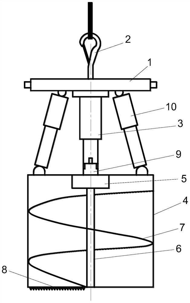
[0019] Such as figure 1 As shown, a debris collection device for drilling and blasting shaft excavation holes, comprising a main beam 1 of a positioning frame, the top of the main beam 1 of the positioning frame is fixedly connected with a hoisting hook 2, and the middle part of the bottom end of the main beam 1 of the positioning frame is connected There is a jacking cylinder 3, the bottom end of the jacking cylinder 3 is connected with a collection bucket 4, and the i...


PUM


Abstract

The invention discloses a debris collecting device for a vertical shaft excavation hole by a drilling and blasting method. The debris collecting device comprises a positioning frame main beam, wherein the top of the positioning frame main beam is fixedly connected with a hoisting hook; the middle part of the bottom end of the positioning frame main beam is connected with a pushing oil cylinder; the bottom end of the pushing oil cylinder is connected with a collecting barrel; a driving motor is fixedly arranged at the top of the inner side of the collecting barrel; an output shaft of the driving motor is connected with a rotating shaft; the rotating shaft is connected with a spiral conveying reamer; the bottom edge of the spiral conveying reamer is fixedly connected with scraping teeth; and the positioning frame main beam, the pushing oil cylinder and the driving motor are connected with a control host. When in use, the debris collecting device is hoisted to the bottom of a shaft by using hoisting equipment, and at the moment, a swing oil cylinder and the pushing oil cylinder are in a retracted state; after the debris collecting device is in place, a hydraulic telescopic beam of the positioning frame main beam extends outwards and is tightly pressed against a reinforced concrete protection wall; and the driving motor operates to twist rock debris below the debris collecting device into the collecting barrel. The debris collecting device realizes automatic cleaning of the debris inside the vertical shaft excavation hole and is beneficial to improving the working efficiency.

Description

technical field [0001] The invention relates to the technical field of debris collection for shaft excavation holes, in particular to a debris collection device for shaft excavation holes by drilling and blasting. Background technique [0002] When using the drill and blast method to excavate hole piles, after the blasting is over, the rock is blasted into debris. In order to create a working face for supporting the rock wall and the next working cycle, the debris needs to be cleaned out of the bottom of the well. [0003] When excavating with manual hole-digging pile technology, it is necessary to manually use a shovel to put the debris in the small bucket, and then use the hoist to lift the keg out of the wellhead and dump it. In this process, affected by the speed of the hoist, the deeper and clearer the well The slower the speed of the slag, and when cleaning the slag, the staff at the bottom of the well are threatened by falling objects, and incidents of falling debris,...

Claims


Application Information

Patent Timeline
IPC IPC(8): E21D1/06E21D1/00E21B27/04
CPCE21D1/06E21D1/00E21B27/04
Inventor 瞿波余讯
Owner 六盘水华安爆破工程有限公司
Learn More