Variable valve structure of internal combustion engine

A technology for internal combustion engines and valves, applied to internal combustion piston engines, combustion engines, non-mechanically actuated valves, etc., can solve problems such as engine burden, energy waves, and unstable gas distribution of the engine, so as to achieve stable gas distribution and reduce energy consumption wasteful effect

Active Publication Date: 2021-11-02
SHANDONG UNIV
View PDF9 Cites 0 Cited by
  • Summary
  • Abstract
  • Description
  • Claims
  • Application Information

AI Technical Summary

Problems solved by technology

Traditional engine valves do not have an adjustable function, and the opening size of the valve is fixed, and the size of the valve cannot be adjusted, which will lead to unstable gas distribution of the engine and cause energy waves.
[0003] The Chinese patent discloses a variable valve lift structure (authorized notification number CN208669372U). The modified patent drives the crank through the driving device, and then the crank drives the swing bar to rotate, and then the swing bar drives the rocker arm to open different valve heights, but The patent requires the addition of a new drive to the engine, which places a heavy burden on the engine

Method used


Image

  • Variable valve structure of internal combustion engine
  • Variable valve structure of internal combustion engine
  • Variable valve structure of internal combustion engine

Examples


Embodiment 1

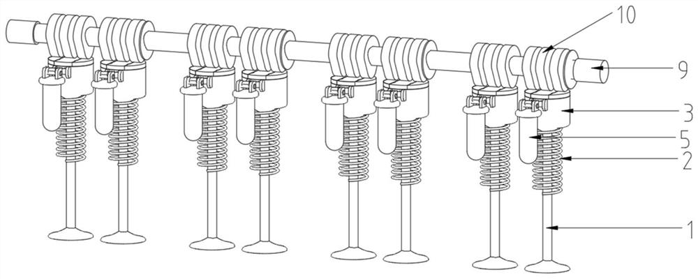
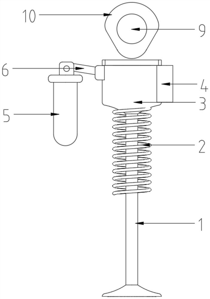
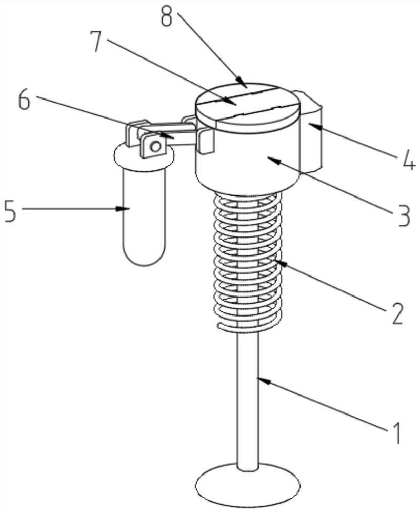
[0029] see Figure 1~5 , in an embodiment of the present invention, a variable valve structure of an internal combustion engine includes a valve assembly, a spring 2, a connecting head 3 and a first rotating shaft 9, the valve assembly is provided with several groups, and the number of each group of valve assemblies is set to two , the first rotating shaft 9 is provided with a number of cam groups, the first rotating shaft 9 is connected to the frame of the internal combustion engine in rotation, and each group of cam groups is provided with six first cams 10, the cam group is located above the valve assembly, the cam group and the valve The components correspond to each other, each set of cam sets corresponds to two sets of valve assemblies, and every three first cams 10 in the cam sets correspond to one set of valve assemblies, and the valve assemblies include a valve stem 1, a spring 2, a connector 3, a control box 4 and Hydraulic tappet 5, the lower end of the valve stem 1...

Embodiment 2

[0036] see Image 6 , 7 , 8, the difference in connection with the basis of Embodiment 1 is that the first rotating shaft 9 is covered with a number of rocker arms 103, the number of rocker arms 103 is the same as the number of valve assemblies, and the number of rocker arms 103 and valve assemblies are one by one Correspondingly, the rocker arm 103 is rotationally connected with the first rotating shaft 9, one end of the rocker arm 103 is in contact with the connector 3, and the other end is rotationally connected with a push rod 104, and the end of the push rod 104 away from the rocker arm 103 is provided with an adjustment rod 105, the second The left side of the first rotating shaft 9 is provided with a second rotating shaft 101, the second rotating shaft 101 is rotationally connected with the internal combustion engine frame, the second rotating shaft 101 is provided with a plurality of second cams 102, and the inside of the adjusting rod 105 is provided with a first adso...


PUM


Abstract

The invention discloses a variable valve structure of an internal combustion engine, and belongs to the field of internal combustion engines. The variable valve structure comprises valve assemblies, springs, connectors and a first rotating shaft, a plurality of groups of valve assemblies are arranged, the number of the valve assemblies in each group is two, the first rotating shaft is sleeved with a plurality of cam groups, six first cams are arranged in each cam set, the cam sets are located above the valve assemblies, and each valve assembly comprises a valve rod, the spring, the connector, a control box and a hydraulic tappet. According to the variable valve structure of the internal combustion engine, the height of a movable block can be higher than that of a fixed block through adjusting devices in the connectors, and then the opening degree of the valve of the internal combustion engine can be controlled under the cooperation of the first cams and the movable block, so that air distribution of the internal combustion engine is more stable, and energy waste is reduced.

Description

technical field [0001] The invention relates to the field of internal combustion engines, in particular to a variable valve structure of the internal combustion engine. Background technique [0002] The function of the valve is to be responsible for inputting air into the engine and discharging the exhaust gas after combustion. From the structure of the engine, it is divided into intake valve and exhaust valve. The role of the intake valve is to draw air into the engine and mix it with fuel for combustion; the role of the exhaust valve is to discharge the burned exhaust gas and dissipate heat. Traditional engine valves do not have an adjustable function, and the opening size of the valves is fixed, and the size of the valves cannot be adjusted, which will lead to unstable gas distribution of the engine and cause energy waves. [0003] The Chinese patent discloses a variable valve lift structure (authorized notification number CN208669372U). The modified patent drives the c...

Claims


Application Information

Patent Timeline
Patent Type & Authority Applications(China)
IPC IPC(8): F01L13/00F01L1/053F01L3/10F01L9/20F01L9/40F01L1/18
CPCF01L13/00F01L1/053F01L3/10F01L9/20F01L9/40F01L1/183Y02T10/12
Inventor 孔羽
Owner SHANDONG UNIV
Why Eureka
Try Eureka