Mixing device with multi-rotational-flow structure
A technology of mixing device and swirl plate, which is applied in the direction of muffler, exhaust device, exhaust treatment, etc., can solve problems such as uneven mixing of ammonia gas, easy crystallization of urea, and excessive size of the mixer, so as to reduce the risk of crystallization , Low risk of crystallization
- Summary
- Abstract
- Description
- Claims
- Application Information
AI Technical Summary
Problems solved by technology
Method used
Image
Examples
Embodiment 1
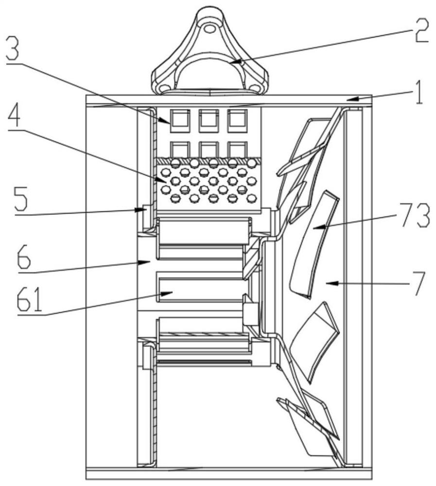
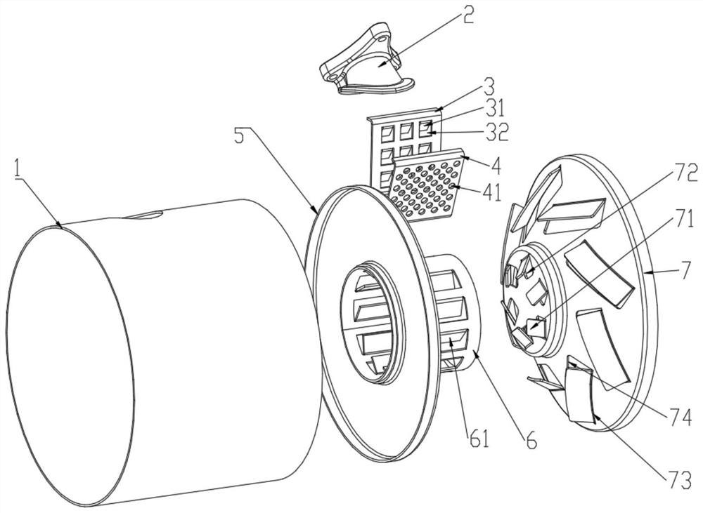
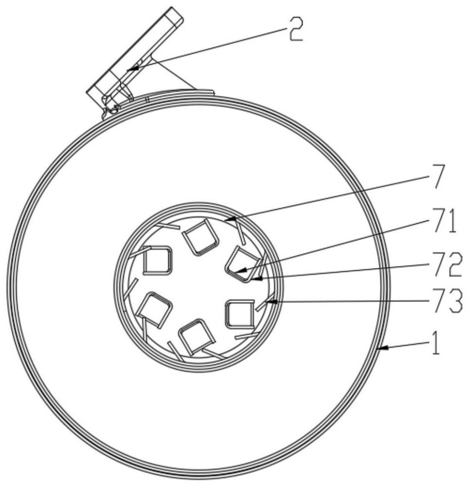
[0027] Such as Figure 1-4 As shown, a multi-swirl structure mixing device includes a cylinder body 1, the two ends of the cylinder body 1 are open, the side wall is provided with a nozzle base 2, and the inside of the cylinder body 1 is provided with a swirl flow structure. The swirl structure includes an upper crushing plate 3, a lower crushing orifice plate 4, a baffle 5, a swirl tube 6 and a swirl plate 7, one end of the swirl tube 6 is connected to the baffle 5, and the other end is connected to the swirl On the plate 7, the baffle plate 5 is arranged at the inlet end of the cylinder body 1, the swirl plate 7 is arranged at the gas outlet end of the cylinder body 1, the upper crushing plate 3 and the lower crushing orifice plate 4 It is arranged inside the barrel 1 where the nozzle base 2 is located, and the lower ends of the upper crushing plate 3 and the lower crushing orifice 4 are connected to the swirl tube 6 , and the left sides are fixed on the baffle 5 .
[0028]...
PUM
 Abstract
Description
Claims
Application Information
 - R&D
- Intellectual Property
- Life Sciences
- Materials
- Tech Scout
- Unparalleled Data Quality
- Higher Quality Content
- 60% Fewer Hallucinations
Browse by: Latest US Patents, China's latest patents, Technical Efficacy Thesaurus, Application Domain, Technology Topic, Popular Technical Reports.
© 2025 PatSnap. All rights reserved.Legal|Privacy policy|Modern Slavery Act Transparency Statement|Sitemap|About US| Contact US: help@patsnap.com


