Aqueous urea solution decomposing mixing device

A technology of urea aqueous solution and mixing device, which is applied in the direction of silencer, exhaust device, exhaust treatment, etc., and can solve the problems of not easy to form crystals on the inner wall of the end cover, low cost of parts and assembly, cost of parts and assembly Advanced problems, to achieve the effect of reducing crystallization risk, low assembly cost, and low component cost

Pending Publication Date: 2020-02-21
无锡亿利环保科技有限公司
View PDF1 Cites 5 Cited by
  • Summary
  • Abstract
  • Description
  • Claims
  • Application Information

AI Technical Summary

Problems solved by technology

[0004] The applicant aims at the high pressure drop of the mixed air flow in the packaging system between the DPF and the SCR in the above-mentioned existing post-processing, crystallization is easily formed on the inner wall surface of the transition shell and the transition post plate, and the air flow mixing uniformity is not high enough, zero Due to the disadvantages of high component cost and assembly cost, a urea aqueous solution decomposition and mixing device with a reasonable structure is provided, the air flow pressure of the mixed air flow is reduced, crystals are not easily formed on the inner wall of the end cover, the air flow mixing uniformity is high, and the cost of parts and assembly is relatively low. Low

Method used


Image

  • Aqueous urea solution decomposing mixing device
  • Aqueous urea solution decomposing mixing device
  • Aqueous urea solution decomposing mixing device

Examples


Embodiment Construction

[0044] The specific implementation manner of the present invention will be described below in conjunction with the accompanying drawings.

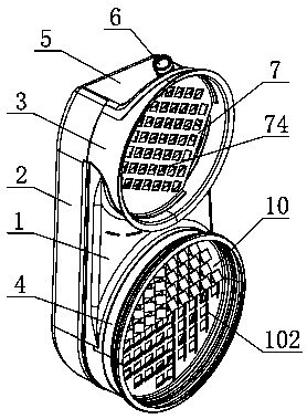
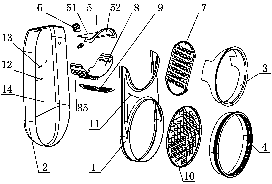
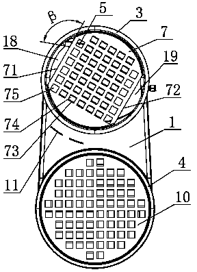
[0045] Such as figure 1 As shown, the front shell 1 of the present invention is fixed on the rear shell 2, and the top of the rear shell 2 is fixedly provided with a top cover 5, and the front shell 1, the rear shell 2, and the top cover 5 are surrounded by an internal cavity 14; The cover 5 is provided with a nozzle seat 6, and the urea nozzle extends into the inner cavity 14 through the nozzle seat 6 (not shown in the figure); an air intake cylinder 3 is installed between the top cover 5 and the upper part of the front shell 1, and the air intake cylinder The air inlet channel of 3 is embedded with a deflector 7, the deflector 7 is provided with a guide vane 74, the lower part of the front shell 1 is equipped with an outlet tube 4, and the outlet channel of the outlet tube 4 is embedded with a swirl plate 10, The swirl plate 10 has swir...


PUM


Abstract

The invention discloses an aqueous urea solution decomposing mixing device. A spoiler and a pore plate are arranged between a front shell and a rear shell. The spoiler and the pore plate divide an inner cavity into an upper spraying cavity, a middle flow guide cavity and a lower rotational flow cavity. A top cover is arranged at the top of the rear shell. An inclined plane is arranged in the spraying cavity, and an included angle is formed between the vertical plane and the inclined plane. A flow guide plate is provided with a flow guide vane. The spoiler is provided with a turbulent flow vane. A rotational flow plate is provided with a rotational flow vane outwards through a third vane hole. The inner cavity of the aqueous urea solution decomposing mixing device is divided into the spraying cavity, the flow guide cavity and the rotational flow cavity only through the spoiler and the pore plate. Little blocking occurs in an airflow channel, the airflow channel is smoother, mixed airflow passes through few turning points in the airflow channel, energy loss is small, and the airflow pressure drop is low. The top cover is provided with an inclined lower plane, and the spraying cavityforms a cavity which is asymmetric along the vertical plane. A nozzle seat is located in a low position of the lower plane, and thus the urea spraying line is toward the direction directly facing thedirection of the turbulent flow vane of the spoiler.

Description

technical field [0001] The invention relates to the technical field of after-treatment of automobile exhaust, in particular to a urea aqueous solution decomposition and mixing device. Background technique [0002] With the continuous growth of the number of automobiles, the pollution of the atmospheric environment by the emission of automobile exhaust is becoming more and more serious. Nitrogen oxides (NOx) from car engines X ) is one of the main sources of air pollution. In order to reduce the pollution of engine emissions to the atmosphere, it is necessary to treat the exhaust emissions of automobile engines. At present, automobile engines usually use selective catalytic reduction technology (SCR) to post-treat exhaust emissions. The urea aqueous solution in the urea tank is sprayed into the exhaust pipe through the urea injection system, and the urea aqueous solution is decomposed into ammonia gas at the temperature of the exhaust gas ( NH 3 ), under the action of cata...

Claims


Application Information

Patent Timeline
Patent Type & Authority Applications(China)
IPC IPC(8): F01N3/20F01N3/28
CPCF01N3/2066F01N3/28F01N2610/02F01N2610/14Y02T10/12
Inventor 乔宝英牛雨飞朱海艳薛红娟李江飞田入园苏赵琪
Owner 无锡亿利环保科技有限公司
Why Eureka
Try Eureka