Infrared thermal image telescope control system

An infrared telescope and control system technology, applied in the field of infrared thermal imaging telescope control system, can solve the problems of complex control structure of infrared thermal imaging telescope and the like

Pending Publication Date: 2021-11-02
SUN CREATIVE ZHEJIANG TECH CO LTD
View PDF7 Cites 0 Cited by
  • Summary
  • Abstract
  • Description
  • Claims
  • Application Information

AI Technical Summary

Problems solved by technology

[0003] The technical problem solved by the present invention is to construct a control system for infrared thermal imaging teles

Method used


Image

  • Infrared thermal image telescope control system
  • Infrared thermal image telescope control system
  • Infrared thermal image telescope control system

Examples


Embodiment Construction

[0018] The technical solutions of the present invention will be further described below in conjunction with specific embodiments.

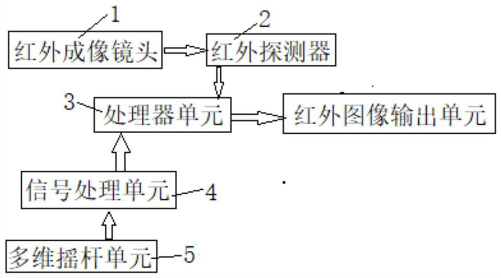
[0019] Such as figure 1 As shown, the specific embodiment of the present invention is: build a kind of infrared thermal imaging telescope control system, comprise infrared imaging lens 1, infrared detector 2, ARM processor unit 3, joystick unit 5, signal processing unit 4, infrared telescope Housing (not shown in the figure), the infrared telescope housing is provided with a supporting part, the ARM processor unit 3 is connected to the infrared detector 2 and the rocker unit 5, and the rocker unit 5 passes through the The infrared telescope housing is fixed on the support part, and the infrared imaging lens 1 converges the long-wave infrared light in a spectral region to the infrared detector 2, which is converted into a digital signal by the infrared detector 2, and then The image signal is processed by the ARM processor unit 3, and the rocker u...


PUM


Abstract

The invention relates to an infrared thermal image telescope control system. A rocker unit is arranged, the rocker unit is connected with a signal processing unit, a first potentiometer and a second potentiometer are connected with the signal processing unit, and the signal processing unit comprises a first-stage signal amplifier and a second-stage signal amplifier; the first potentiometer and the second potentiometer are connected with the first-stage signal amplifier, and the first-stage signal amplifier is connected with the second-stage signal amplifier; an ARM processor unit comprises an electrical level driving circuit; the second-stage signal amplifier is connected with the electrical level driving circuit; an enter key is connected with the electrical level driving circuit; and the ARM processor unit performs corresponding control on an infrared telescope according to a signal of the electrical level driving circuit. Therefore, the size of the whole machine is reduced, and meanwhile, a user can conveniently control the infrared telescope.

Description

technical field [0001] The invention relates to a rocker control system, in particular to an infrared thermal imaging telescope control system. Background technique [0002] At present, most monocular infrared thermal imaging telescopes on the market use jog buttons to realize human-computer interaction. Each jog button corresponds to a function. The more complicated it is, in order to reduce the weight of the whole machine, the volume of the monocular infrared thermal imaging telescope cannot be increased, and the smaller the volume of the button will cause difficulty in operation. It is urgent to need a button that can realize multiple functions. For infrared thermal imaging telescopes using ARM processors, the continuously changing analog voltage signals of traditional buttons cannot be recognized, and special circuits need to be used for processing. Contents of the invention [0003] The technical problem to be solved by the invention is to construct a control system ...

Claims


Application Information

Patent Timeline
IPC IPC(8): G05B19/042
CPCG05B19/0423G05B2219/25257
Inventor 曾华雄万培荣
Owner SUN CREATIVE ZHEJIANG TECH CO LTD
Why Eureka
Try Eureka