
Production method of wire harness and wire harness

A production method and wire harness technology, applied in the field of electronic components, can solve the problems of high processing cost and complex production process, achieve the effects of high molding efficiency, increase the application environment, and ensure the effect of insulation protection

Active Publication Date: 2021-11-02
CHANGCHUN JETTY AUTOMOTIVE PARTS CORP
View PDF8 Cites 3 Cited by
  • Summary
  • Abstract
  • Description
  • Claims
  • Application Information

AI Technical Summary

Problems solved by technology

[0004] The object of the present invention is to provide a production method of a wire harness and a wire harness, so as to relieve the wire harness for electrically connecting electrical devices, the production process is relatively complicated, and the processing cost is relatively high technical issues

Method used


Image

  • Production method of wire harness and wire harness
  • Production method of wire harness and wire harness
  • Production method of wire harness and wire harness

Examples


Embodiment 1

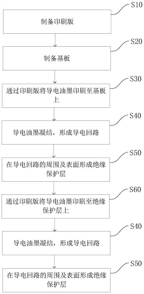
[0066] The invention provides a production method of a wire harness, such as figure 1 As shown, the production method of the wiring harness includes: step S10, preparing a printing plate; step S20, preparing the substrate 10; step S30, printing conductive ink on the substrate 10 through the printing plate; step S40, condensing the conductive ink to form a conductive circuit 21 ; Step S50 , forming an insulating protective layer 40 around and on the surface of the conductive circuit 21 .

[0067] The production method of the wire harness adopts the method of conductive ink printing to form a conductive loop 21 on the substrate 10, and the conductive loop 21 can be connected with external electrical devices to realize the electrical connection function of the wire harness; and the insulating protection layer 40 is used for insulation protection, thereby Realize rapid prototyping of wiring harness loops. By adopting the production method of the wire harness, the forming efficien...

Embodiment 2

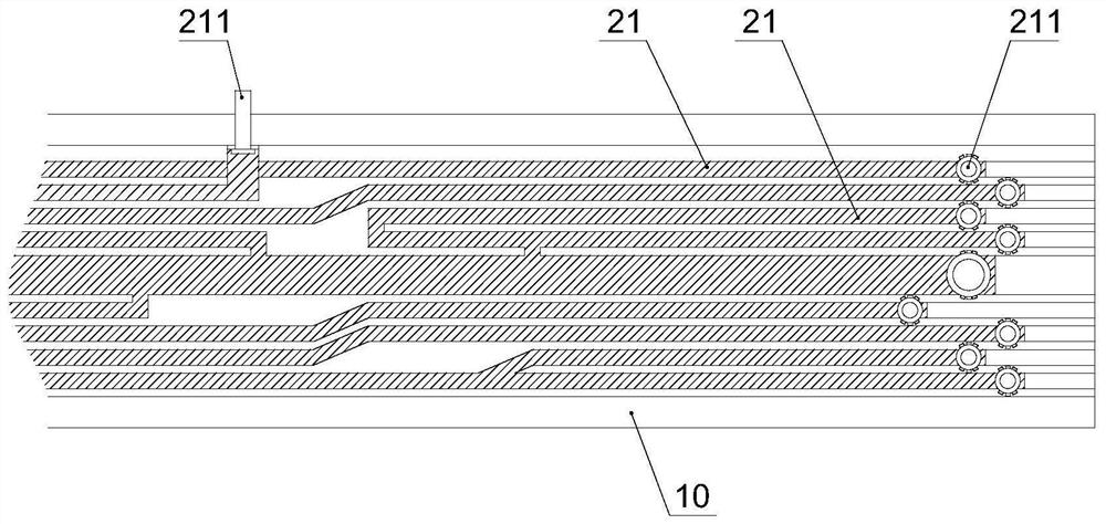
[0100] The present invention provides a wire harness, which is produced by the above wire harness production method. The wire harness includes: a substrate 10, at least one conductive circuit 21 and at least one insulating protective layer 40, and each conductive circuit 21 is located between the substrate 10 and the outermost Between the insulating protection layers 40 of the layers, the conductive loops 21 and the insulating protection layers 40 are alternately distributed. The wire harness is suitable for automatic, large-scale and rapid production, the conductive loop 21 can be formed at one time, the production automation degree is relatively high, the efficiency is high, and the production cost is reduced; it is convenient for installation and disassembly, and the assembly efficiency is improved.

[0101] In one embodiment, the section width of the conductive loop is 0.1mm-68mm. In the wiring harness, the cross-sectional area of ​​the conductor determines the current tha...


PUM

PropertyMeasurementUnit
widthaaaaaaaaaa
widthaaaaaaaaaa
breakdown field strengthaaaaaaaaaa

Abstract

The invention provides a production method of a wire harness and the wire harness. The production method of the wire harness comprises the steps of S10 preparing a printing plate; S20 preparing a substrate; S30 printing conductive ink on the substrate through the printing plate; S40 condensing the conductive ink to form a conductive loop; and S50 forming an insulating protection layer around and on the surface of the conductive loop. According to the invention, the technical problems of relatively complex production process and relatively high processing cost of the wire harness for electrically connecting an electric device are solved.

Description

technical field [0001] The invention relates to the technical field of electronic components, in particular to a production method of a wire harness and the wire harness. Background technique [0002] The electrical connection of vehicles, household appliances, etc., needs to be realized by wiring harness. The existing wiring harness is mainly composed of electric wires, terminals, sheaths, positioning parts and brackets, etc., with many parts, complicated structure, complicated processing technology and low degree of automation. [0003] PCB (Printed Circuit Board, printed circuit board) can quickly realize dense electrical circuit forming, but PCB is suitable for integrated circuits, it is difficult to apply to the electrical connection of electrical equipment, especially for the electrical connection of large equipment. The cost of PCB production equipment is relatively high, and the production process is relatively complicated. The production process of PCB includes etc...

Claims


Application Information

Patent Timeline
Patent Type & Authority Applications(China)
IPC IPC(8): H01B13/00H01B13/06H01B13/22H01B7/02H01B7/17
CPCH01B13/00H01B13/06H01B13/22H01B7/02H01B7/17H01B7/0045
Inventor 王超苗云
Owner CHANGCHUN JETTY AUTOMOTIVE PARTS CORP
Learn More