Log centering device with good centering effect for log processing

A centering device and log technology, applied in wood processing equipment, metal processing equipment, manufacturing tools, etc., can solve problems such as loosening of screw joints, waste of resources, and low utilization rate of logs

Pending Publication Date: 2021-11-05
JIANGSU JIANGHAI MACHINE TOOLS GROUP
View PDF10 Cites 5 Cited by
  • Summary
  • Abstract
  • Description
  • Claims
  • Application Information

AI Technical Summary

Problems solved by technology

"However, the parts used to fix the log in this device cannot be disassembled from the device, and it is inconvenient to replace the fixing components of different sizes according to the size of the log;
[0006] 3. The comparative document CN212825204U discloses a fixing device for round wood processing, "comprising a fixing frame and a sliding bracket, and the sliding bracket is placed on the fixing frame; One waist of the trapezoidal bump is provided with a roller, and the other waist is provided with a meshing gear. The roller and the meshing gear form an inverted trapezoidal structure. There is also a pressing frame assembly above the roller and the meshing gear. The rollers are far away from the trapezoid. One end of the projection is also connected with the first rocker; the pressing frame assembly includes a top frame and a positioning assembly, one end of the top frame is hinged on the side of the fixed frame provided with one end of the trapezoidal projection, and the other end is connected to the side of the fixed frame The opposite side; the positioning assembly is arranged on the top of the top frame; the positioning assembly includes a second handle, a screw and a limit block connected sequentially from top to bottom; the utility model solves the problem of the entire log in the prior art. The utilization rate of the remaining round logs after cutting is not high, waste of resources, and the fixing effect of the round log fixing device is not good, etc.
"However, in this device, the motor used to drive the logs to rotate vibrates relatively strongly, and the vibration force is transmitted through the solids between the components in the device, which can cause some screw joints in the device to loosen.

Method used


Image

  • Log centering device with good centering effect for log processing
  • Log centering device with good centering effect for log processing
  • Log centering device with good centering effect for log processing

Examples


Embodiment 1

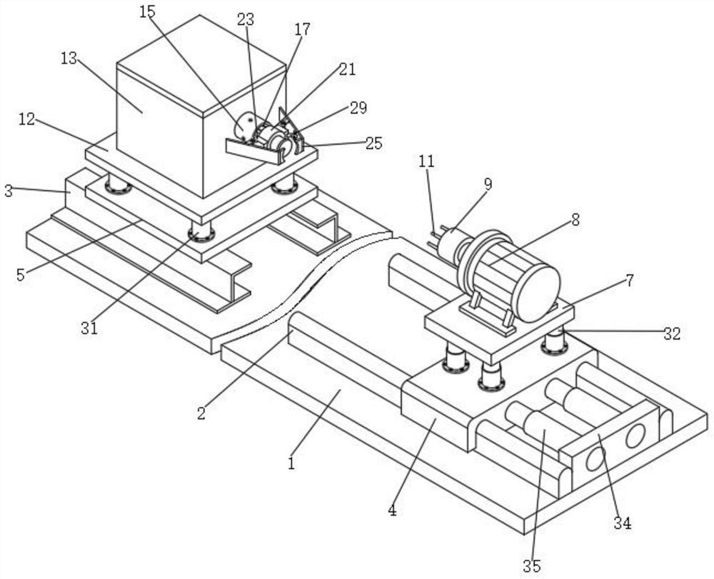
[0040] Such as figure 1 and Figure 8 As shown, a log centering device with good centering effect for log processing includes a base plate 1, a sliding rod 2 and a folding part 3. Two sets of sliding rods 2 arranged in front and behind are installed on the top of the base plate 1, and the top of the base plate 1 is installed There is a folding part 3, and the folding part 3 is located on one side of the slide bar 2;

[0041] Specifically, the bottom plate 1 is used for the sliding bar 2 and the folding part 3 in the combined device, so that the components installed on the top of the sliding bar 2 and the components installed on the top of the folding part 3 can be on the same group of plates, and then form a whole , in order to center the log, the top of the slide bar 2 is arc-shaped, which can reduce the time when the slide plate 4 moves toward or away from the folded part 3 on the outer surface of the slide bar 2 under the push or pull of an external force The received fri...

Embodiment 2

[0047] Such as Figure 5 , Figure 6 and Figure 7 As shown, the tops of the other five groups of telescopic springs 6 are provided with connecting plates 12, and the connecting plates 12 are located above the fixed plate 5, the top of the connecting plates 12 is equipped with a protective frame 13, and the bottom wall of the protective frame 13 is equipped with a rotating motor 14 , the output end of the rotating motor 14 is equipped with a rotating shaft, one end of the rotating shaft is equipped with a connecting cylinder 15, and one end of the connecting cylinder 15 extends out of the inside of the protective frame 13, and the inside of the connecting cylinder 15 is evenly equipped with six groups of fittings arranged in a ring. Block 16, the outer surface of the connecting cylinder 15 is provided with three sets of through grooves.

[0048] The inner wall of the connecting cylinder 15 is equipped with engaging columns 17, and the outer surface of the engaging columns 17...

Embodiment 3

[0053] Such as Figure 4 As shown, the front and back of the cylinder 21 are equipped with connecting blocks 23, and the outer walls of the two groups of connecting blocks 23 away from the cylinder 21 are equipped with two groups of flat plates arranged up and down, wherein the tops of the two groups of flat plates and the tops of the other two groups of flat plates Bottoms are equipped with movable plates 24, wherein splints 25 are installed on the backs of two groups of movable plates 24 arranged up and down and on the fronts of other two groups of movable plates 24 arranged up and down, and movable bars 26 are installed on the tops of two groups of movable plates 24 , and the bottoms of the two groups of movable rods 26 respectively pass through the insides of the other two groups of movable plates 24 , and the outer surfaces of the movable rods 26 are surrounded by spring groups 27 .

[0054]Two groups of splints 25 are equipped with a movable shaft 28 on one side of the o...


PUM


Abstract

The invention discloses a log centering device with a good centering effect for log processing. The log centering device comprises a bottom plate, sliding rods and folding pieces, the two sets of sliding rods arranged front and back are installed at the top of the bottom plate, and the folding pieces are installed at the top of the bottom plate. Sliding plates are installed on the outer surfaces of the two sets of sliding rods correspondingly, a fixing plate is installed at the tops of the two sets of folding pieces, and multiple sets of telescopic springs are installed at the top of the fixing plate and the tops of the sliding plates correspondingly. A storage plate is installed at the tops of four sets of telescopic springs, and a servo motor is installed at the top of the storage plate. According to the log centering device, one end of a log can be fixed through steel needles, meanwhile, the other end of the log can be attached to the outer wall of a rubber sleeve through pushing force generated when electric telescopic rods extend outwards, the other end of the log is doubly fixed, and thus the situation that the log is thrown out of the device under driving of rotating force is avoided; parts for fixing in the device are detachable, and thus size replacement is facilitated; and vibration can be counteracted through the springs when two sets of motors in the device operate.

Description

technical field [0001] The invention relates to the field of centering technology, in particular to a log centering device with good centering effect for log processing. Background technique [0002] In the field of log processing, the log needs to be fixed before various processing of the log, and the log centering device is required to fix the log. Generally, a biaxial fixation can be used to fix the two ends of the log so that the log can be fixed during the processing process. Not easy to shift, not easy to drop. [0003] The defective that existing log processing device exists is: [0004] 1. Comparative document CN110587729A discloses a kind of self-centering automatic feeding wood processing lathe which saves process micro-distance adjustment, "comprising machine frame, turning position, seat frame, feeding frame, machine frame is provided with turning position, machine frame and The seat frame is locked, the seat frame is installed and connected with the feeding fr...

Claims


Application Information

Patent Timeline
Patent Type & Authority Applications(China)
IPC IPC(8): B27C9/00B24B41/06B24B41/00B24B19/24
CPCB27C9/00B24B41/06B24B41/00B24B19/24
Inventor 陈友华赵呈龙郭正阳
Owner JIANGSU JIANGHAI MACHINE TOOLS GROUP
Why Eureka
Try Eureka